The JDY-31 is a fairly simple Bluetooth 3.0 SPP module than can be used as a HC-06 replacement. It should be noted that it is not a direct replacement though as the AT commands are not identical.
Bluetooth 3.0 is still Bluetooth classic but has an increased theoretical transmission speed of up to 24 Mbps.
JDY-31s are available with and without a breakout board.
The SMD boards are 3.3v only so take care. The breakout board adds 5v VCC in compatibility but the RX and TX pins are still 3.3v only. So you still need to take care!
I have the SMD no pins boards. I bought these to solder directly to a PCB.
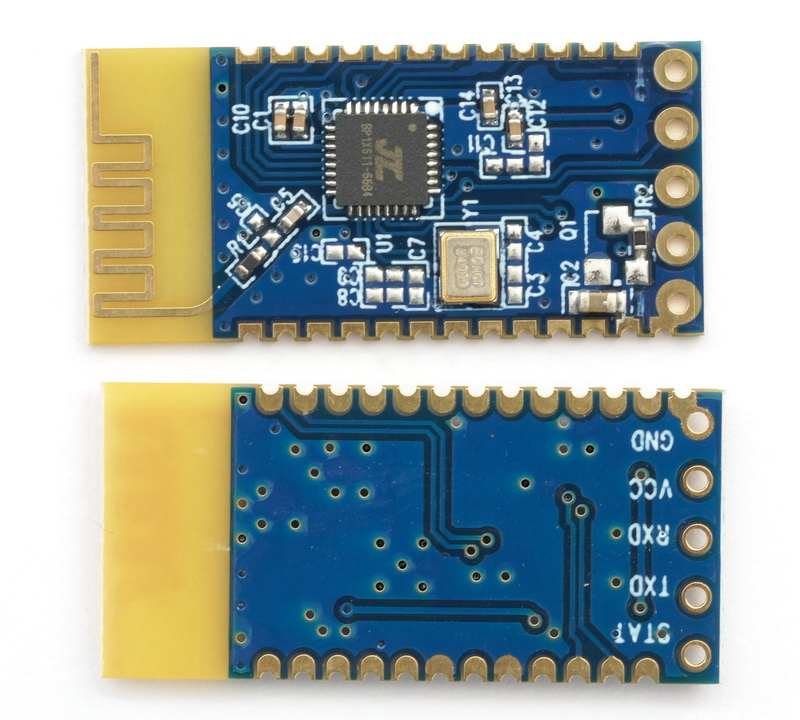
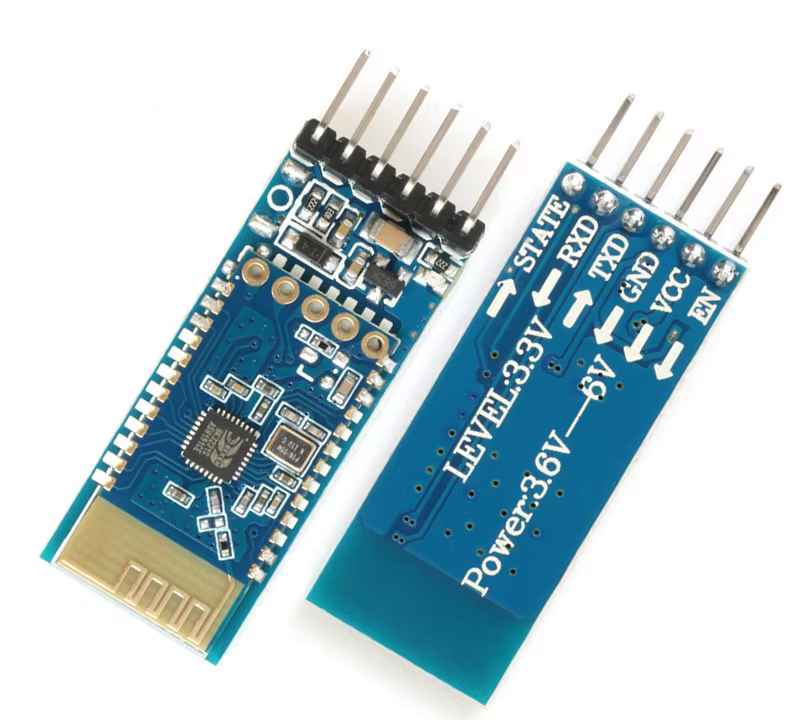
JDY-31 Basic Specifications
Slave only device
Bluetooth 3.0 SPP / Bluetooth Classic compatible
Will work reliably up to 30 meters (HC-06s are 10 meters)
Configured via AT commands via hardwired serial UART
The default PIN (used for pairing) is 1234
The SMD module has 5 pins. The breakout board version has 6 pins
Slave only devices cannot initiate a connection. Another device (such as an Android phone) has to make the connection.
JDY-31 V1.3 English datasheet (PDF)
JDY-31 SMD Module Pins
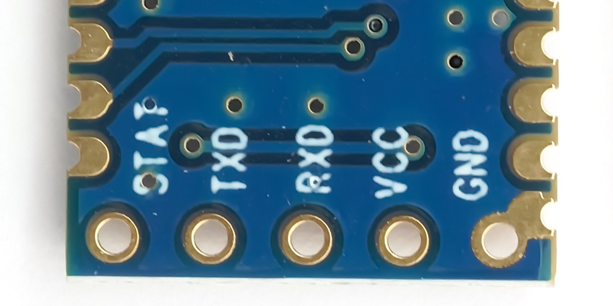
STATE – Connection status. LOW = not connected. HIGH = connected
TXD – Serial UART out
RXD – Serial UART in
VCC – VCC in (remember 3.3v)*
GND – GND
*The JDY-31 SMD module can also be used at 1.8v
JDY-31 Breakout Board Pins
The breakout boards are pretty standard and used for many different Bluetooth modules.
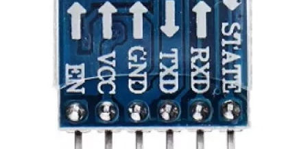
STATE – Connection status. LOW = not connected. HIGH connected
TXD – Serial UART out (3.3v)
RXD – Serial UART in (3.3v)
VCC – VCC in (3.6v to 5v)
GND – GND
EN – not normally connected
The breakout board normally includes a status LED.
JDY-31 AT Commands
Although the JDY-31 has more AT commands than the HC-06, the list of commands is still fairly limited. There is no basic AT command but you can query the modules name via serial UART which is a bonus.
Since there is no AT command to check that the serial UART connection is working just use the AT+VERSION command instead.
The default baud rate is 9600 and the JDY-31 expects (NO, DEMANDS!) that commands are in upper case and end of line characters (\r\n) are added.
| Command | Description | Default Value |
| AT+VERSION | Check the firmware version number | JDY-31-V1.2* |
| AT+RESET | Soft reset the module | |
| AT+DISC | Disconnects the current connection. Can be used when the module is wirelessly connected. | |
| AT+LADDR | Queries the modules MAC address. | |
| AT+PIN | Query / set the PIN code. The PIN code is used for device pairing. | 1234 |
| AT+BAUD | Query / set the serial UART baud rate | 9600 |
| AT+NAME | Query / set the modules broadcast name | JDY-31-SPP |
| AT+DEFAULT | Resets the module to the default settings | |
| AT_ENLOG | Serial port status output enable | 1 |
* JDY-31-V1.2 is the latest version. earlier versions can still be found.
Talking to the JDY-31 Bluetooth Module
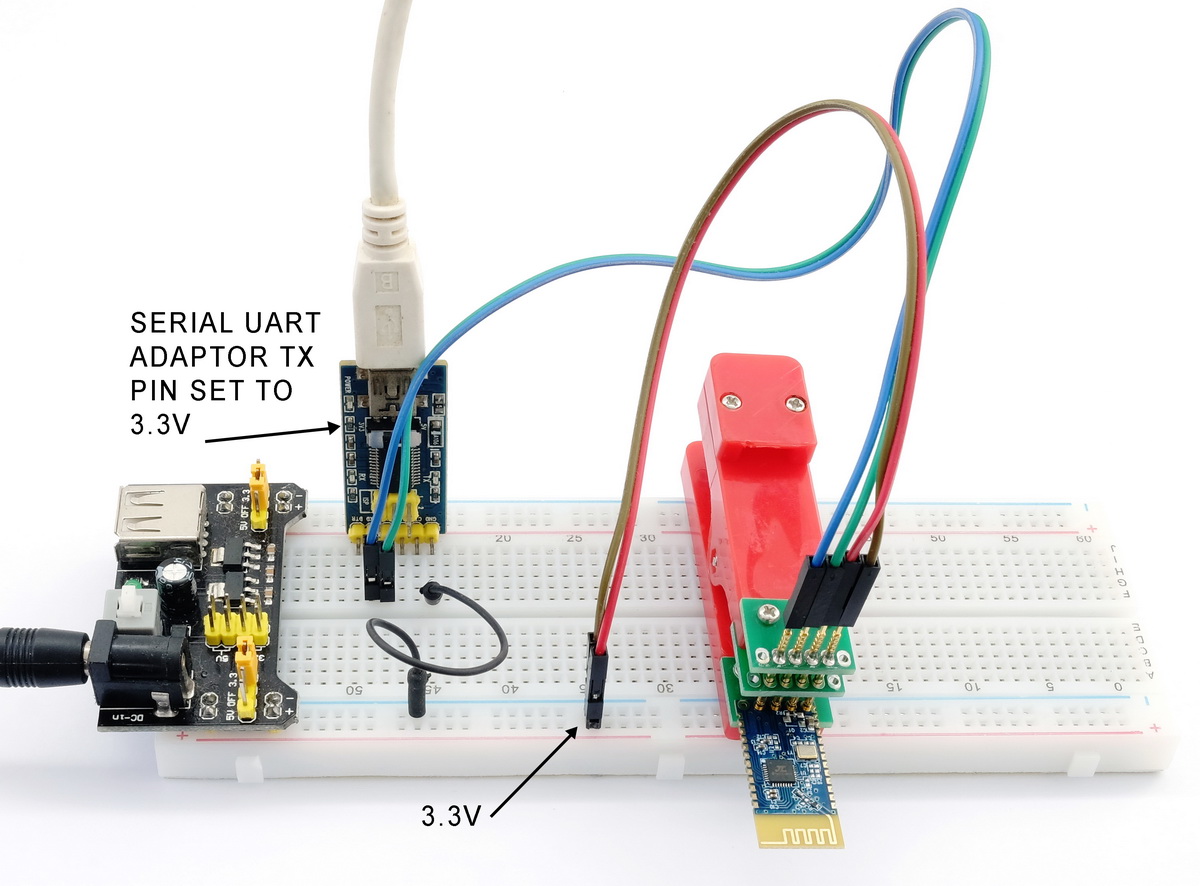
First we need to connect up the module. I am using the SMD modules which are 3.3v and do not have pins. Therefore, I have a slightly messy circuit using a pogo pin programming springy connector thingy.
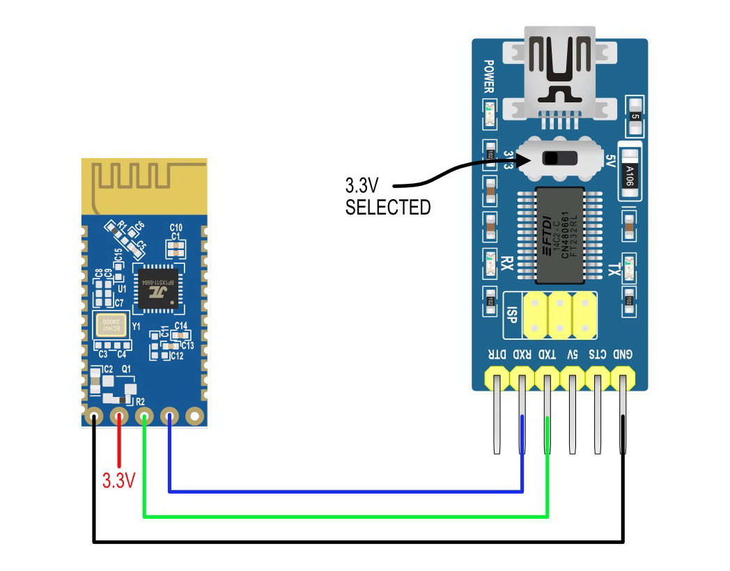
Circuit 1. Using a USB To Serial Adaptor
I am using a breadboard power supply to get the 3.3v required for the JDY-31 module.
The USB to serial UART adaptor is 5v/3.3v switchable and has 3.3v selected.
JDY-31 RX connected to USB serial UART adaptor TX pin (set to 3.3v)
JDY-31 TX connected to USB serial UART adaptor RX pin
JDY-31 VCC to 3.3v
GNDS are connected
JDY-31 STATE pin is not connected.
It will be easier using the breakout board modules. Just remember that the JDY-31 RX pin is 3.3v.
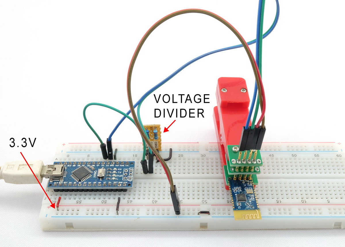
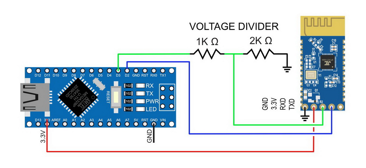
Circuit 2 Using An Arduino With A Serial Pass-Through Sketch
JDY-31 RX pin to Arduino D2
JDY-31 TX pin to Arduino D3 via a voltage divider (5v to 3.3v)
JDY-31 VCC in to Arduino 3.3v out
GND to GND
The Arduino sees 3.3v as HIGH, therefore, the JDY-31 TX pin (which is 3.3v) can be connected directly to the Arduino RX pin without the need to step up the voltage to 5v.
Arduino Serial Pass-Through Sketch
The Arduino sketch uses the software serial library with D2 as the Arduino TX and D3 as Arduino RX.
/*
 *  sketch: SerialPassThrough_SoftwareSerial_Basic
 *  martyncurrey.com
 *
 *  Use software serial to talk to serial/UART connected device
 *  Whatever is entered in the serial monitor is sent to the connected device
 *  Anything received from the connected device is copied to the serial monitor
 *
 *  Pins
 *  BT VCC to Arduino 5V out or Arduino 3.3V out.
 *  BT GND to GND
 *  Arduino D2 (Arduino RX) goes to module TX
 *  Arduino D3 (Arduino TX) goes to module RX. May need a voltage divider.
 *
 *  Assumes a 5V Arduino is being used
 *  If the connected device is 3.3v add a voltage divider (5v to 3.3v) between Arduino TX and device RX
 *  Arduino RX to device TX does not need a voltage divider. The Arduino will see 3.3v as high
 *
 */

#include <SoftwareSerial.h>
SoftwareSerial softSerial(2, 3); // RX, TX

char c=' ';

void setup()
{

    Serial.begin(9600,SERIAL_8N1 );
    while (!Serial) { ; }

    Serial.print("Sketch:   ");   Serial.println(__FILE__);
    Serial.print("Uploaded: ");   Serial.println(__DATE__);

    softSerial.begin(9600);
    Serial.println("softSerial started at 9600");
    Serial.println("Ready");
}


void loop()
{
    // Read from the Serial Monitor and send to the UART module
    if (Serial.available())
    {
        c = Serial.read();
         softSerial.write(c);
    }


    // Read from the UART module and send to the Serial Monitor
    if (softSerial.available())
    {
        c = softSerial.read();
        Serial.write(c);
    }

} // void loop()
Check the JDY-31 Broadcast Name
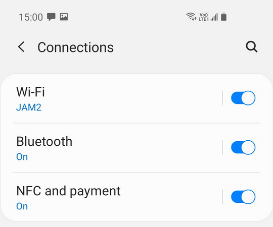
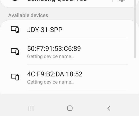
Before trying some AT commands, lets check that the module is on and broadcasting. Connect the JDY-31 to power and use an Android device to scan for Bluetooth devices.
On my phone it’s Settings => Connections -> Bluetooth. Yours may (or may not) be different.
Scan for devices and if the planets are aligned, JDY-31-SPP appears in the list.
Using AT Commands
To talk to the JDY-31 I am using Simple Serial Monitor (an Arduino IDE Serial Monitor replacement). If you don’t have Simple Serial Monitor and don’t want it then the Arduino IDE will be nearly as good :-)
Open Simple Serial Monitor (or the Arduino IDE Serial Monitor)
select 9600 baud rate
set line end characters to NL and CR (\r\n)
select the correct COM port (either the USB to serial adaptor or the Arduino) and click connect.
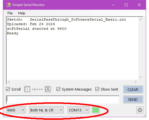
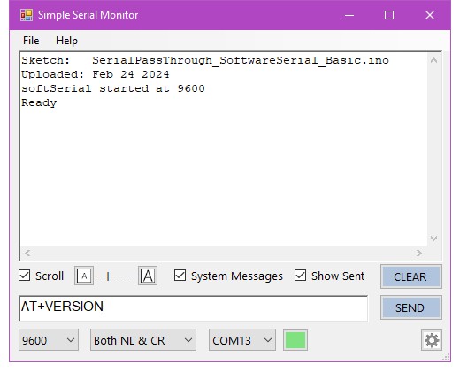
If you are using the Arduino with serial pass through you will see the start up message.
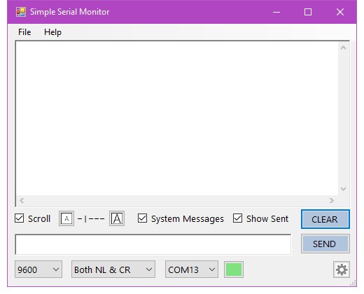
If you are using a USB to serial UART adaptor you get nowt.
For the rest of this guide I will be using the Arduino circuit.
AT+VERSION
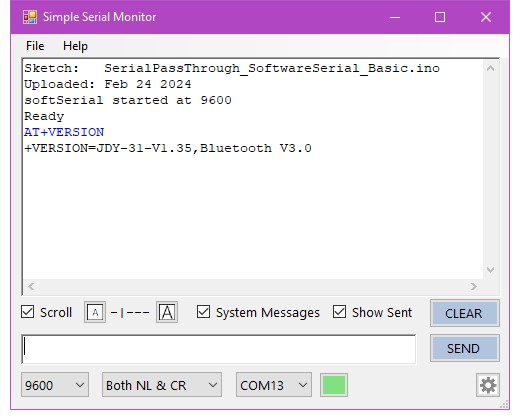
Since there is no AT command lets start with AT+VERSION
Enter AT+VERSION and click SEND
You should see the modules firmware version
AT+NAME
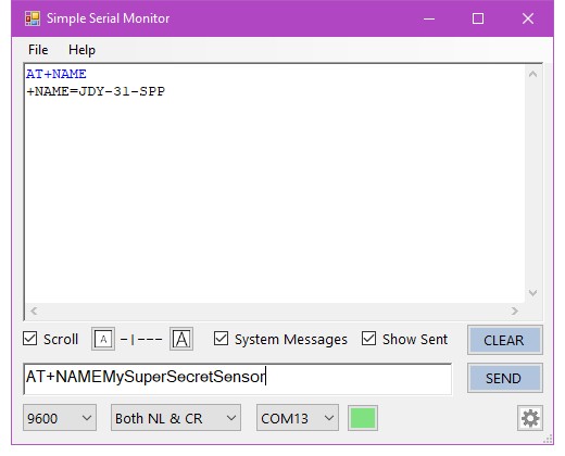
To confirm what the module is calling itself use AT+NAME
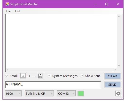
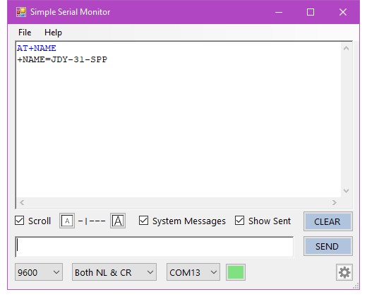
and to change the name, use AT+NAME again. This time add the new name to the command.
Enter AT+NAMEMySuperSecretSensor and hit SEND. Note there is no =.
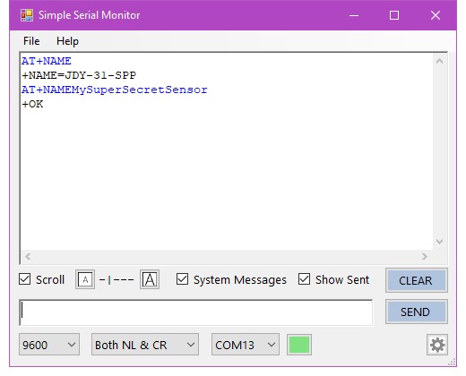
If the JDY-31 likes the new name it will replay with a +OK
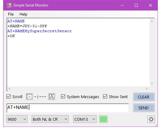
You can double check the new name has been accepted by redoing the AT+NAME command
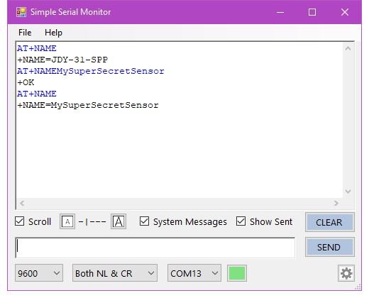
To reset the modules name use AT+NAMEJDY-31-SPP, or, if you haven’t changed any of the other settings AT+DEFAULT
AT+DEFAULT
AT+DEFAULT resets all the settings back to their original factory settings.
AT+DEFAULT seems to mess up the AT+NAME command.
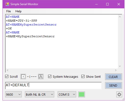
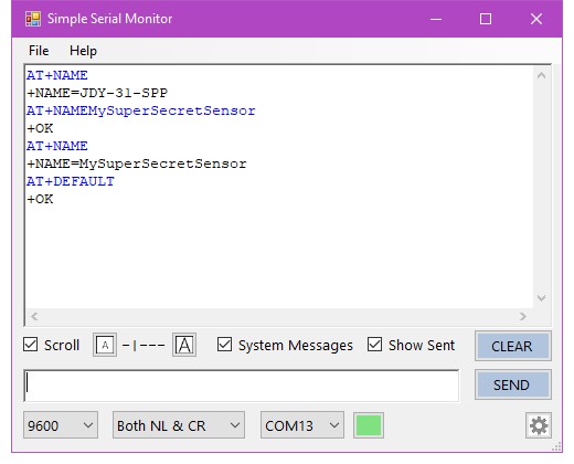
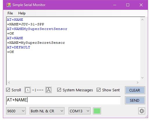
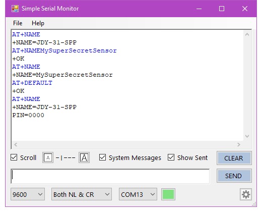
Use AT+NAME again to confirm the name has reset to the original.
You should notice that the module now includes PIN=0000 message. This is done to mess with you, the PIN code is really 1234.
AT+PIN
To check what the current PIN code is, use
AT+PIN
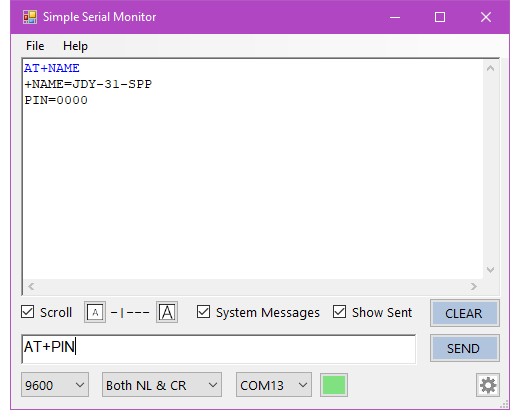
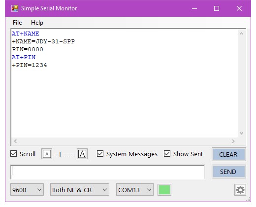
You may be surprised to learn it is
1234
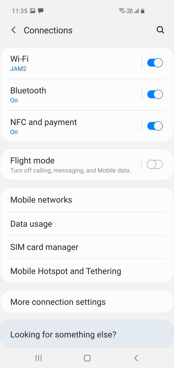
You can check the PIN code by using an Android device to pair with the JDY-31. Using your Android device of choice, go to Settings => Connections
Open up Bluetooth
Let the device Scan until you see the JDY-31
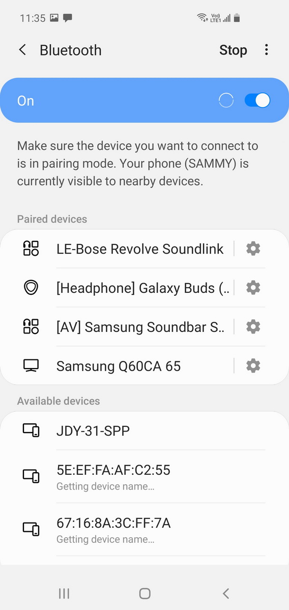
Click on the JDY-31 entry. You will be asked to enter the PIN code. First try 0000 and hit OK
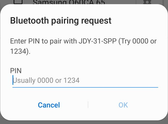
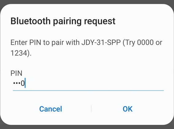
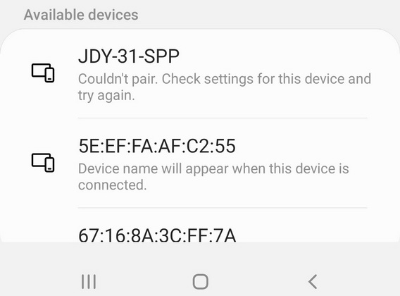
The Android device fails to connect.
HA HA! The JDY-31 fooled you!
Try again with 1234
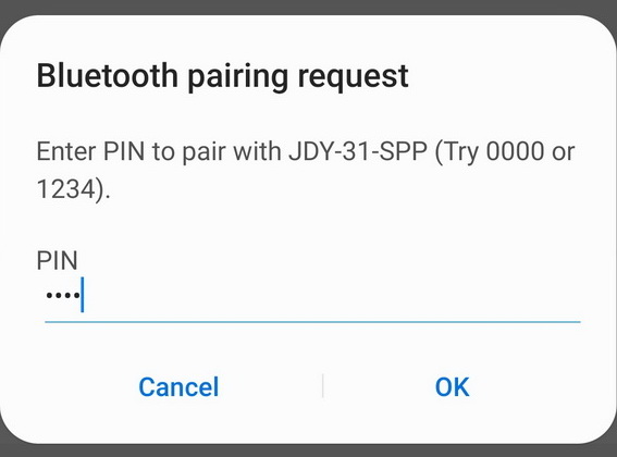
Success!. The JDY-31 is now paired.
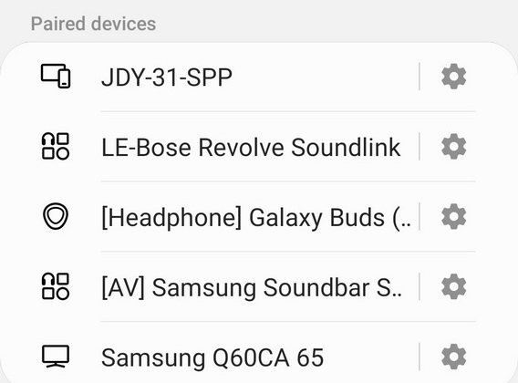
Android Phone To JDY-31
Since we have the Android device open with the JDY-31 paired we might as well use it to send messages to the Arduino. To do this we need a Bluetooth terminal app. I am using Serial Bluetooth Terminal by Kai Morich available on the Google Play Store.
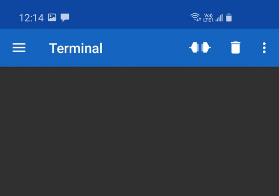
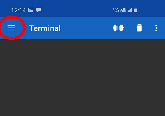
Open the app and click the menu icon
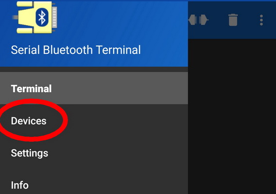
Open Devices
Click the JDY-31-SPP entry.
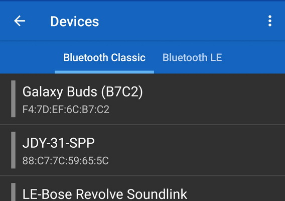
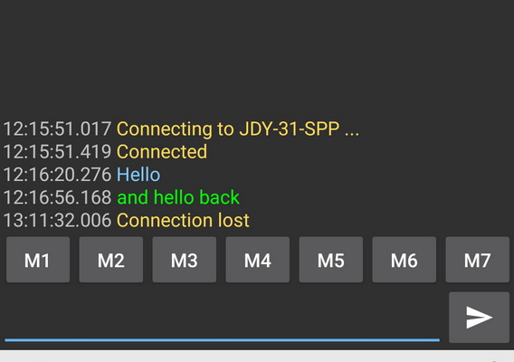
The app will try to connect.
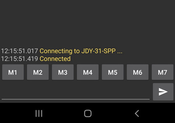
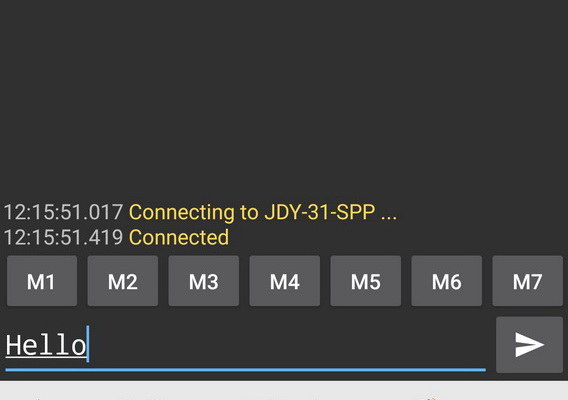
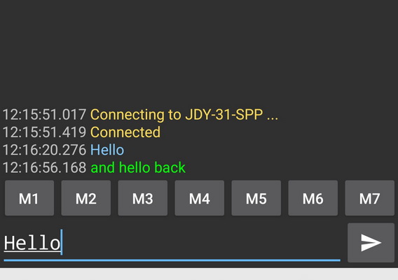
If the connection is successful, enter Hello and hit send
and be amazed, Amazed!, when Hello appears in the serial monitor
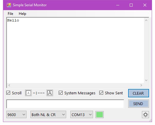
In the serial monitor, enter and hello back, click SEND
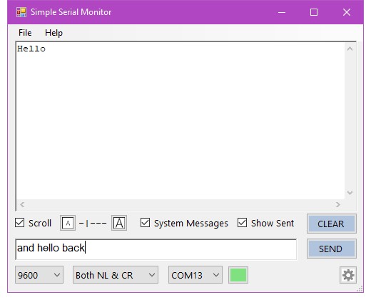
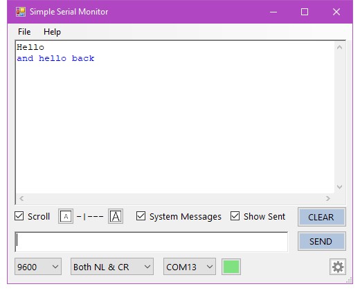
and low and behold, the message appears before you. Exciting times.
AT+DISC
While there is an active wireless connection, sending AT+DISC via the serial UART channel cancels the connection.
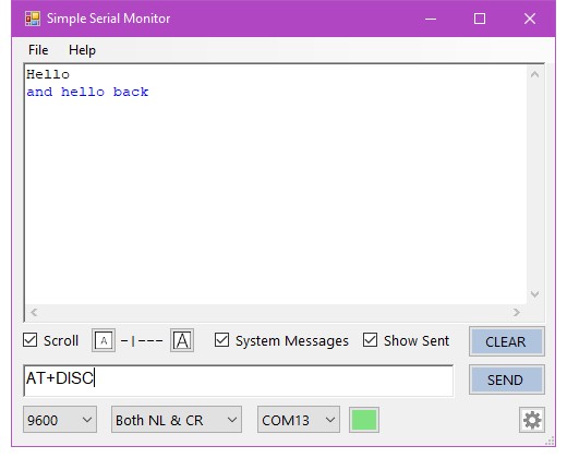
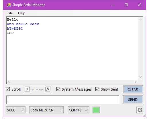
Connection lost
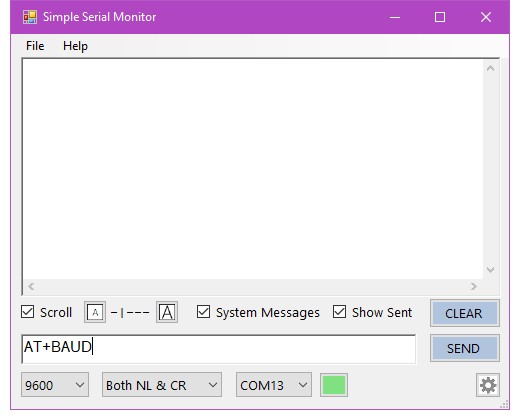
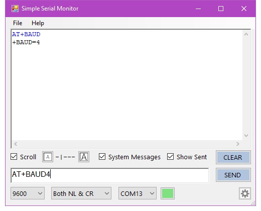
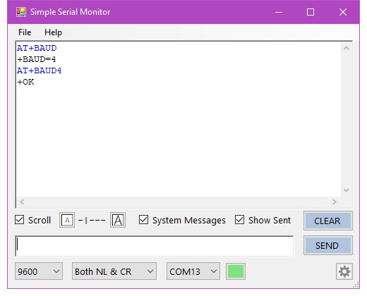
AT+BAUD
To check what the current baud rate is, use AT+BAUD. To use this command you need to connect to the JDY-31 with the correct baud rate first, so this commands just confirms what you already know!
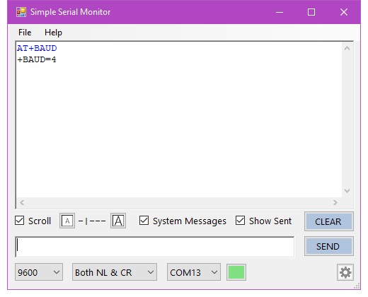
The JDY-31 has a limited range of baud rates:
- 4: 9600
- 5: 19200
- 6: 38400
- 7: 57600
- 8: 115200
- 9: 128000
To set A different speed use AT+BAUDindexnum, where indexnum is from 4 to 9
AT+BAUD4 sets the baud rate to 9600.
Amazon is selling boards JDY-31A
https://www.amazon.com/dp/B0CFTS98GV
AT+VERSION returns
‘JDY-31A-V2.241, Bluetooth V3.0+BLE’