Although Part 2 was more advanced than part 1, part 2 still only sent data one-way, from the Arduino to the Visual Basic app, and the data was very basic. It’s time to spice things up with more complex commands and 2-way communication.
Although I used the sketch and Visual Basic app from the previous guide as my starting point, the sketch and app in this part are quite a bit more complex.
- I have made the commands more informative / complex
- I added sending data from the app
- I added receiving data on the Arduino
- I added some fancy bits like turning the app slider off when not in use. (Yes I know you don’t know anything about a slider, it’s coming…)
Circuit
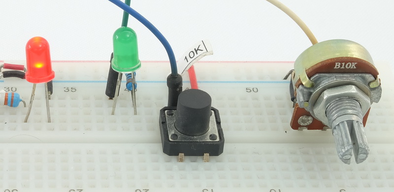
The circuit is the same as before, except I added a green LED and moved the red LED and button switch over.
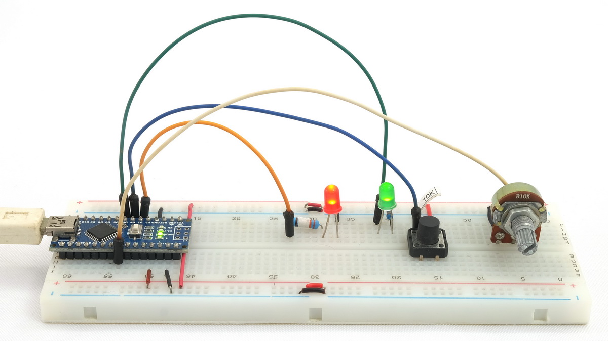
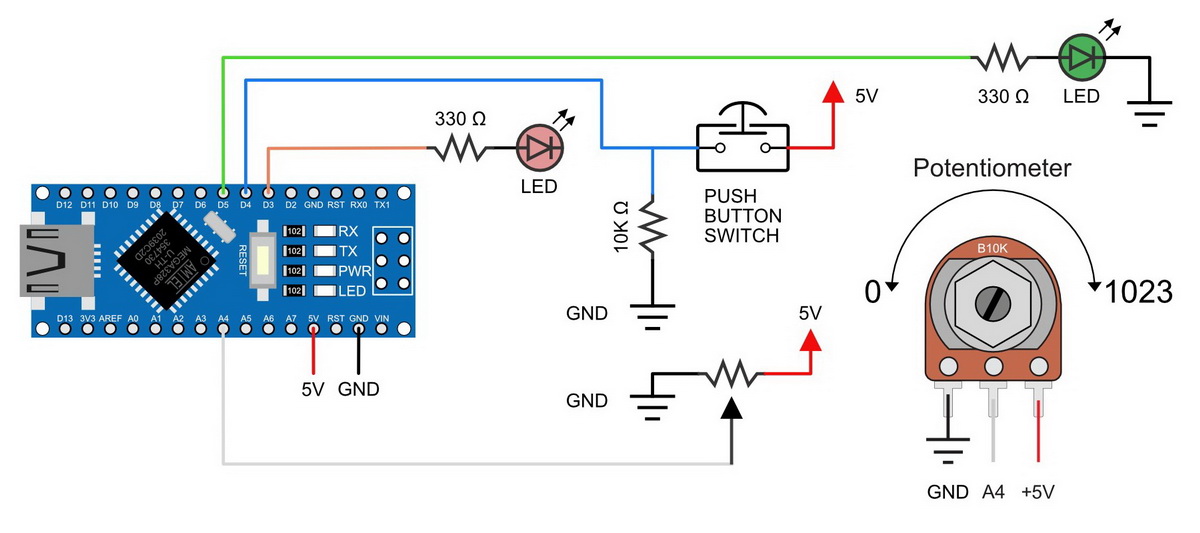
D3 – red LED + resistor
D4 – push button switch
D5 – green LED + resistor
A4 – potentiometer
On the Arduino side:
- Red LED. The LED being controlled.
- Green LED. Used to show when the Arduino has control.
- Button switch. Used to toggle what has control.
- Potentiometer. Used to set the LED brightness.
The button switch is used as a toggle switch to turn the LED on and off
Green LED ON = Arduino has control
Green LED off = VB app has control
The push button switch is used to toggle what has control. It turns the green LED on and off.
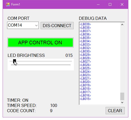
Visual Basic App Form
Some things are new, other things have moved.
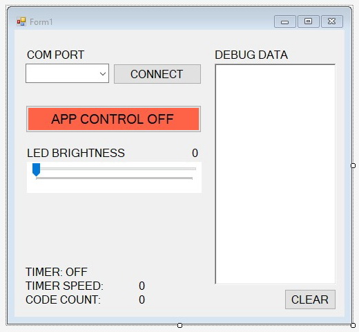
COM PORT & CONNECT button
Select the desired COM port and click connect.
DEBUG DATA text box
Shows internal data such as received commands. Data received is in black, data sent out is in blue, and anything else is in red.
APP CONTROL button
Toggles what has control over the LED, either the Arduino or the app
LED BRIGHTNESS slider/trackbar
When the Arduino has control, the slider shows the LED brightness value.
When the app has control, the slider sets the LED brightness.
TIMER label
Shows when the check serial in timer is active
TIMER SPEED
Shows the timer tick frequency in milliseconds.
CODE COUNT
This shows the number of data packets received so far.
CLEAR button.
Clears the DEBUG DATA text box and resets CODE COUNT
Why Have A Control Function?
The potentiometer has a manually fixed position and it’s value cannot be set from the VB app. If you do not disable/ignore the potentiometer while the app is sending new LED brightness data, the potentiometer would simply over write it.
If you need/want/would simply like to have both controls active all the time you need to use something that does not have a physically set value such as a rotary encoder or motorised potentiometer.
Give It A Go
Set up the Arduino, upload the sketch.
Download the Visual Basic project, open in Visual Studio and click the little Start button at the top.
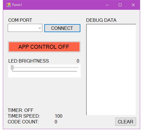
Select your COM port and click the CONNECT button
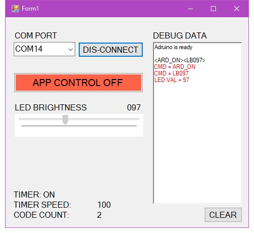
The app should connect to the Arduino and start to receive commands.
The LED BRIGHTNESS slider will adjust to show the led brightness
As commands are received they are displayed in the DEBUG DATA test box. Anything in black is data received by the app.
Arduino is ready – start up message
<ARD ON> – This tells the app that the Arduino has control
<LB097> – LB (LED Brightness) is the current PWM value (097) given to the red LED. The PWM value is simply the potentiometer value divided by 4. 0-1023 / 4 = 0-255
Any data received that is not inside start and end markers (the < and >) is ignored by the app.
Anything in red is internal data.
Turn the potentiometer and the LED should dim or become bright. The new LED brightness value is sent to the app and the slider position is adjusted accordingly.
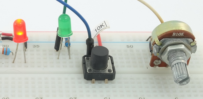

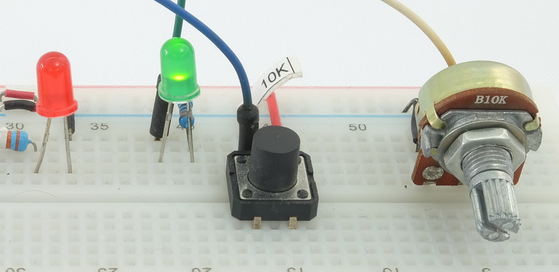
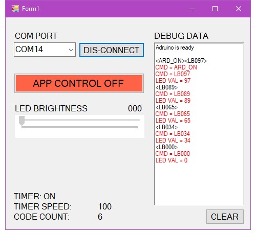
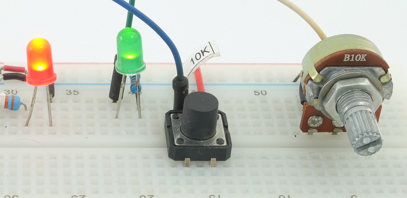

Now either press the push button switch on the breadboard or click the APP CONTROL button is the app.
I used the button switch. On the breadboard the green LED goes out. In the app the APP CONTROL button turns green.
You can see the <ARD OFF> command in the DEBUG DATA text box. It;s this command that tell the app to take control.
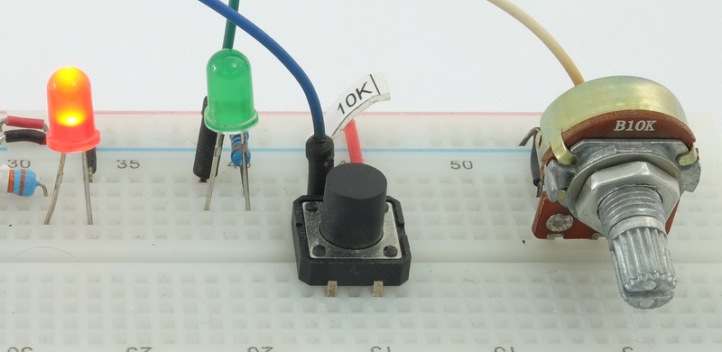
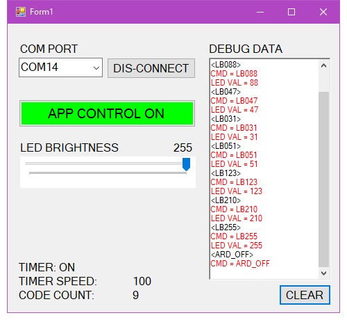
Now the potentiometer does not do anything and the LED can only be controlled by the slider in the app.
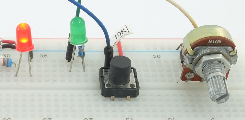

Play around with the controls, dis-connect and reconnect, clear the debug information.
Arduino Sketch
A bit more complex than in the previous guide and to make the main loop() easier to read, the main code blocks have been moved to their own functions.
/*
* Sketch Arduino and Visual Basic Part 3
* Send and receive between Arduino and Visual Basic
* https://www.martyncurrey.com/arduino-and-visual-basic-part-3-receiving-data-from-the-arduino/
*
* potentiometer used to control LED PWM
* push button switch, turn LED on and off
*/

/*
* Pins
* D3 - LED + resistor
* D4 - push button switch
* D5 - control LED + resistor
* A4 - potentiometer
*/

// When DEGUG is TRUE print newline characters
// Useful when using the serial monitor
const boolean DEBUG = false;

const byte redLedPin       = 3;
const byte buttonSwitchPin = 4;
const byte controlLEDPin   = 5;
const byte potPin          = A4;

boolean newSwitchState1 = LOW;
boolean newSwitchState2 = LOW;
boolean newSwitchState3 = LOW;
boolean oldSwitchState  = LOW;

unsigned int oldPotVal = 0;
unsigned int newPotVal = 0;
const int potUpdateFreq = 200;  //  how often the potentiometer is read
long timeNow  = 0;
long timePrev = 0;

// used to hold an ascii representation of a number [10] allows for 9 digits
char numberString[10];

boolean haveNewData = false;
boolean ArduinoHasControl = false;  // false used for off

char recDataBuffer [31];
int length = 30;


void setup()
{
  pinMode(redLedPin, OUTPUT);       digitalWrite(redLedPin ,LOW);
  pinMode(controlLEDPin , OUTPUT);  digitalWrite(controlLEDPin  ,LOW);

  pinMode(buttonSwitchPin, INPUT);

  Serial.begin(115200);
  while (!Serial) {;}
  Serial.println("Adruino is ready");
  Serial.println(" ");

  Serial.print("<ARD_ON>");
  if (DEBUG) { Serial.println(""); }
  turnArduinoControlOn();
}


void loop()
{
  checkSerialIn();
  if (haveNewData)   { processNewData(); }

  checkPushButtonSwitch();

  if (ArduinoHasControl)
  {
      timeNow = millis();
      if (timeNow - timePrev >= potUpdateFreq )
      {
            timePrev = timeNow;
            updatePotentiometer();
      }
  }

}  //  loop()


void turnArduinoControlOn()
{
  ArduinoHasControl = true;
  oldPotVal =0;
  updatePotentiometer();
  digitalWrite(controlLEDPin ,HIGH);
}

void turnArduinoControlOff()
{
  ArduinoHasControl = false;
  digitalWrite(controlLEDPin,LOW);
}


void checkSerialIn()
{
	// checks serial in.
	// if data is available, and if the start marker is received, copies it to a buffer
	// when the end marker is received stop copying and set haveNewData = true
	static boolean recvInProgress = false;
	static byte ndx = 0;
	char startMarker = '<';
	char endMarker = '>';
	char rc;
	if (Serial.available() > 0)
	{
		rc = Serial.read();
		if (recvInProgress == true)
		{
			 if (rc != endMarker)
			 {
				recDataBuffer[ndx] = rc;
				ndx++;
				if (ndx > length) { ndx = length; }
			 }
			 else
			 {
				 recDataBuffer[ndx] = '\0'; // terminate the string
				 recvInProgress = false;
				 ndx = 0;
				 haveNewData = true;
			 }
		}
		else if (rc == startMarker) { recvInProgress = true; }
	}
}


void processNewData()
{

  if      (strcmp(recDataBuffer, "VB_ON")  == 0)  { turnArduinoControlOff();  haveNewData = false; }
  else if (strcmp(recDataBuffer, "VB_OFF") == 0)  { turnArduinoControlOn();   haveNewData = false; }

  // LB = LED Brightness
  else if (recDataBuffer[0] == 'L' && recDataBuffer[1] == 'B' )
  {
      // convert the ascii numbers to an actual number
      int LED_PWN_val = 0;
      LED_PWN_val  =              (recDataBuffer[2] - 48) * 100;
      LED_PWN_val = LED_PWN_val + (recDataBuffer[3] - 48) * 10;
      LED_PWN_val = LED_PWN_val +  recDataBuffer[4] - 48;

      analogWrite(redLedPin,LED_PWN_val);
      haveNewData = false;
  }

	else
	{
		// unknown command
		// issue an error message in some way or simply set haveNewData to false and ignore
		haveNewData = false;
	}

}


void checkPushButtonSwitch()
{
    // check the push button switch pin and if pressed toggle Arduino control / App control

    // simple debounce
    newSwitchState1 = digitalRead(buttonSwitchPin);      delay(1);
    newSwitchState2 = digitalRead(buttonSwitchPin);      delay(1);
    newSwitchState3 = digitalRead(buttonSwitchPin);

    if (  (newSwitchState1==newSwitchState2) && (newSwitchState1==newSwitchState3) )
    {
        if ( newSwitchState1 != oldSwitchState )
        {
            oldSwitchState = newSwitchState1;

           // has the button switch been closed?
           if ( newSwitchState1 == HIGH )
           {
                if ( ArduinoHasControl == false )
                {
                    Serial.print("<ARD_ON>");
                    if (DEBUG) { Serial.println(""); }
										turnArduinoControlOn();
                }
                else
                {
                  Serial.print("<ARD_OFF>");
                  if (DEBUG) { Serial.println(""); }
                  turnArduinoControlOff();
                }
            }
       }
    }

}  //  checkPushButtonSwitch()


void updatePotentiometer()
{
    // get the potentiometer value and set the LED PWN accordingly
    // pot value = 0 to 1023, LED PWN is 0 to 255, so we divide the pot value by 4
    // LED brightness is logarithmic not linera but I don't worry about it here.

    // The potentiometer I am using jitters a bit (cheap breadboard I think) so I only using changes of 5 or more.
    newPotVal = analogRead(potPin);
    if ( abs(newPotVal-oldPotVal) > 4)
    {
        oldPotVal = newPotVal;

        int LED_PWN_val = newPotVal / 4;
        analogWrite(redLedPin,LED_PWN_val);

        formatNumber( LED_PWN_val, 3);
        Serial.print("<LB");
        Serial.print(numberString);
        Serial.print(">");
        if (DEBUG) { Serial.println("");  }
    }

}  // updatePotentiometer()


void formatNumber( unsigned int number, byte digits)
{
    // Formats a number in to a string and copies it to the global char array numberString
    // pads the start of the string with '0' characters
    //
    // number = the integer to convert to a string
    // digits = the number of digits to use.

    char tempString[10] = "\0";
    strcpy(numberString, tempString);

    // convert an integer into a acsii string
    itoa (number, tempString, 10);

    // create a string of '0' characters to pad the number
    byte numZeros = digits - strlen(tempString) ;
    if (numZeros > 0)
    {
       for (int i=1; i <= numZeros; i++)    { strcat(numberString,"0");  }
    }
     strcat(numberString,tempString);
} // formatNumber
The Sketch In Detail
Run through of all the main parts and functions.
Serial.begin()
Serial.begin(115200);If you have looked at the code you may have noticed I have jumped up to 115200 baud rate. While 9600 just about managed with one-way communication from the Arduino, it is not fast enough now that there is a slider sending data. The slider in Visual basic creates an event every time the handle moves and every time the handle moves the new value is sent to the Arduino. This can create a lot of serial traffic.
There are ways to negate this, for example send the new value only after the user has finished moving the handle, but this does not create a smooth user experience.
The way the slider change event is used in the below app means the LED on the Arduino will change brightness while the user is moving the handle and the action is fairly smooth. It does mean there is a lot of serial data to be sent though.
115200 baud rate is fine, even suggested, when using hardware serial. It don’t work for software serial though. The fastest I have successfully used software serial is 38400.
Main loop()
void loop()
{
  checkSerialIn();
  if (haveNewData)   { processNewData(); }

  checkPushButtonSwitch();

  if (ArduinoHasControl)
  {
      timeNow = millis();
      if (timeNow - timePrev >= potUpdateFreq )
      {
            timePrev = timeNow;
            updatePotentiometer();
      }
  }

}  //  loop()
checkSerialIn()
haveNewData and processNewData()
checkPushButtonSwitch()
if the ArduinoHasControl and the time is right call updatePotentiometer()
Now that the Arduino is receiving commands from the app we need to have code that receives the data and then processes it in some way. checkSerialIn() does the receiving, processNewData() does the processing.
checkSerialIn() is based on recvWithStartEndMarkers() by robin2 of the Arduino forum. It checks serial for new data and if it finds some copies the new data to the recDataBuffer global variable buffer. This function is special because it looks for start and end markers and does not start to copy the new data until after it finds the start marker.
When checkSerialIn() finds an end marker it sets haveNewData to true. This is the flag I use to, you guessed it, let me know there is new data :-)
If you want to know more about using start and end markers take a look at Arduino Serial: ASCII Data and Using Markers to Separate Data.
When there is new data (haveNewData is true), processNewData() is called.
processNewData() check the new data for known commands. There are only 3 commands in this example so this function is fairly short.
VB_ON – The Visual Basic app has taken control
VB_OFF – The Visual Basic app has given control to the Arduino
LBnnn – The VB app has changed the LED brightness. nnn is a number from 0 to 255.
When VB_ON is received turnArduinoControlOff() is called, and
when VB_OFF is received turnArduinoControlOn() is called.
turnArduinoControlOff() and turnArduinoControlOn() are short little functions that allow the code they contain to be easily reused. Remember, the push button switch can also be used to change the control setting so using functions means the the same code can be used by the button switch and the serial command from the VB app.
If the function finds LB then it knows this is a LED brightness command. and that there is a 3 digit number after the LB characters.
Any easy way to convert an ascii representation of a number (IE “1”) is to subtract 48 from the ascii value. The ascii code for a “0” is 48, so 48-48 is the value 0. The ascii code “1” is 39, so 49-48 = 1. Simples.
void processNewData()
{

  if      (strcmp(recDataBuffer, "VB_ON")  == 0)  { turnArduinoControlOff();  haveNewData = false; }
  else if (strcmp(recDataBuffer, "VB_OFF") == 0)  { turnArduinoControlOn();   haveNewData = false; }

  // LB = LED Brightness
  else if (recDataBuffer[0] == 'L' && recDataBuffer[1] == 'B' )
  {
      // convert the ascii numbers to an actual number
      int LED_PWN_val = 0;
      LED_PWN_val  =              (recDataBuffer[2] - 48) * 100;
      LED_PWN_val = LED_PWN_val + (recDataBuffer[3] - 48) * 10;
      LED_PWN_val = LED_PWN_val +  recDataBuffer[4] - 48;

      analogWrite(redLedPin,LED_PWN_val);
      haveNewData = false;
  }

	else
	{
		// unknown command
		// issue an error message in some way or simply set haveNewData to false and ignore
		haveNewData = false;
	}
}
checkPushButtonSwitch() checks, you guessed it, the pus button switch. Your getting good at this!
This time though, the button switch is acting as a toggle. I am no longer interested in the button being pressed or not, now I only want to know if its pressed and wasn’t pressed before, and if it is pressed change what has control.
If you want to know about using a button switch take a look at the switching things on and off series.
if ( newSwitchState1 != oldSwitchState )
{
	oldSwitchState = newSwitchState1;

	 // has the button switch been closed?
	 if ( newSwitchState1 == HIGH )
	 {
		if ( ArduinoHasControl == false )
		{
			Serial.print("<ARD_ON>");
			if (DEBUG) { Serial.println(""); }
			turnArduinoControlOn();
		}
		else
		{
			Serial.print("<ARD_OFF>");
			if (DEBUG) { Serial.println(""); }
			turnArduinoControlOff();
		}
	}
If the switch status is HIGH then I know it has changed and I can toggle the status of the ArduinoHasControl variable.
When the sketch jumps back to the main loop() it checks the status of ArduinoHasControl and if the Arduino does indeed have control, and the appropriate amount of time has passed, the potentiometer is checked.
  if (ArduinoHasControl)
  {
      timeNow = millis();
      if (timeNow - timePrev >= potUpdateFreq )
      {
            timePrev = timeNow;
            updatePotentiometer();
      }
  }
Why not use a Delay(200) the same as part 1 and part 2?
The previous sketches were very simple and a short delay didn’t really effect anything. This new sketch has a lot more happening and I didn’t want to make the sketch wait unnecessarily. delay() blocks the sketch. It makes everything wait until it is finished. By using a timer, the sketch keeps on going and only jumps to the potentiometer when it is time to do so.
If you want to know more about using a timer look at the later turning things on and off guides.
updatePotentiometer() reads the value of the potentiometer, checks to see if the value has changed 5 or more, and if it has, updates the PWM signal on the red LED and then sends out the LED Brightness (LB) command.
Why only send when the value has change 5 or more?
Low quality something, either the potentiometer or the breadboard, and this causes the value to jitter. Nobody likes a jittering potentiometer.
void updatePotentiometer()
{
    newPotVal = analogRead(potPin);
    if ( abs(newPotVal-oldPotVal) > 4)
    {
        oldPotVal = newPotVal;

        int LED_PWN_val = newPotVal / 4;
        analogWrite(redLedPin,LED_PWN_val);

        formatNumber( LED_PWN_val, 3);
        Serial.print("<LB");
        Serial.print(numberString);
        Serial.print(">");
        if (DEBUG) { Serial.println("");  }
    }

}
That just leaves some helper functions
turnArduinoControlOn()
turnArduinoControlOff()
formatNumber(…)
turnArduinoControlOn() and turnArduinoControlOff() toggle the device that has control. When control is returned to the Arduino turnArduinoControlOn() also updates the potentiometer straight away.
void turnArduinoControlOn()
{
  ArduinoHasControl = true;
  oldPotVal =0;
  updatePotentiometer();
  digitalWrite(controlLEDPin ,HIGH);
}

void turnArduinoControlOff()
{
  ArduinoHasControl = false;
  digitalWrite(controlLEDPin,LOW);
}formatNumber(…) takes a numeric value (an integer) and converts it to an ascii string. This is a routine I use a lot and simply copy paste in to new sketches when I need it.
formatNumber(…) has two arguments, the number to convert, and the number of digits to use. It puts the converted ascii number in to the global variable called numberString.
The function uses a temporary variable to convert the number, then it creates a string of 0s, and then puts the two together.
void formatNumber( unsigned int number, byte digits)
{
    char tempString[10] = "\0";
    strcpy(numberString, tempString);

    // convert an integer into a acsii string
    itoa (number, tempString, 10);

    // create a string of '0' characters to pad the number
    byte numZeros = digits - strlen(tempString) ;
    if (numZeros > 0)
    {
       for (int i=1; i <= numZeros; i++)    { strcat(numberString,"0");  }
    }
     strcat(numberString,tempString);
}
And that’s it for the sketch.
Visual Basic App
The app, while not the largest every created, is certainly a lot larger than the previous one. I used the app from part 2 as the starting point and went for it. As well as adding the code to handle the new elements I also added some basic error trapping on the serial port.

The Visual Basic code it getting fairly long so I won’t waste space by listing it here. If you want a quick look, click here to load a text file of the code.
Compared to the previous app, there are now many more small functions/routines. These allow the code inside the functions to be easily reused.
The logic of the VB app is a bit more complex and now includes actions that can be caused by two or more events. For example, closing the serial connection can be caused by the user clicking the DIS-CONNECT button or if there is an error reading or writing to the COM port, the Arduino being turn off for example. These events happen in different places in the code but require the same response. Rather than having two or more pieces of identical code, the code has been put in to a function and the function called.
Visual Basic App Main Parts
Let’s start with when the app first starts and closes. As before, when the app first runs, Form1_Load() is called. Here is where I do any initialising stuff. New for part 3 are:
AppControlButtonOff()
turnAppControllOff()
These set up the app in the off state. AppControlButtonOff() simply disables the App Control button.
    Private Sub Form1_Load(ByVal sender As System.Object, ByVal e As System.EventArgs) Handles MyBase.Load
        Timer1.Enabled = False
        selected_COM_PORT = ""
        For Each sp As String In My.Computer.Ports.SerialPortNames
            comPort_ComboBox.Items.Add(sp)
        Next

        TimerSpeed_value_lbl.Text = Timer1.Interval
        AppControlButtonOff()
        turnAppControllOff()
    End Sub


    Private Sub MainForm_FormClosing(sender As Object, e As FormClosingEventArgs) Handles MyBase.FormClosing
        If (SerialPort1.IsOpen) Then
            Try
                SerialPort1.Close()
            Catch ex As Exception
                MessageBox.Show("Serial Port is already closed!")
            End Try
        End If
    End Sub
AppControlButtonOff() disables the the App Control button. A sister function, AppControlButtonOn(), enables the button.
The App Control button is enabled/disabled from different places in the app, and while using functions is not necessary in this example, functions are used in case I expand the code later and want to add other things, like change the button colour or the button text colour. I then only need to update the code in one place.
    Private Sub AppControlButtonOn()
        CONTROL_BTN.Enabled = True
    End Sub

    Private Sub AppControlButtonOff()
        CONTROL_BTN.Enabled = False
    End Sub
turnAppControllOff() updates the screen to show that the VB app no longer has control. There is a sister function called turnAppControllOn() that updates to show the VB has control.
    Private Sub turnAppControllOn()
        CONTROL_BTN.Text = "APP CONTROL ON"
        CONTROL_BTN.BackColor = Color.Lime
        SLIDER_trackBar.Enabled = True
    End Sub

    Private Sub turnAppControllOff()
        CONTROL_BTN.Text = "APP CONTROL OFF"
        CONTROL_BTN.BackColor = Color.Tomato
        SLIDER_trackBar.Enabled = False
    End Sub
The app has started and is now waiting for the user to select a COM PORT and click the CONNECT button. COM port is a comboBox drop down list.

Selecting a COM PORT is handled by comPort_ComboBox_SelectedIndexChanged(…). It is called when the value in the drop down list changes and all this does is copy the newly selected port to the selected_COM_PORT global variable
 Private Sub comPort_ComboBox_SelectedIndexChanged(sender As Object, e As EventArgs) Handles comPort_ComboBox.SelectedIndexChanged
        If (comPort_ComboBox.SelectedItem <> "") Then
            selected_COM_PORT = comPort_ComboBox.SelectedItem
        End If
    End Sub
Selecting a COM port and connecting to serial
When the CONNECT button is clicked, connect_BTN_Click(…) is called. This forst thing this function does is check to see if the user is connecting or dis-connecting. This is done by looking at the button text, either CONNECT or DIS_CONNECT
If the button text is CONNECT then the function tries to open a serial connection using the previously selected COM port. The process is wrapped in a try/catch to catch any problems. This allows the app to handle issues rather than letting the app crash.
If the button text says DIS-CONNECT then the serial connection is closed.
Finally, checkSerialPortandUpdateScreen() is called. checkSerialPortandUpdateScreen() updates the screen.
Private Sub connect_BTN_Click(sender As Object, e As EventArgs) Handles connect_BTN.Click
    If (connect_BTN.Text = "CONNECT") Then
        If (selected_COM_PORT <> "") Then

            ' Try allows me to trap an errors such as the COM port not being available
            ' Without it the app crashes.
            Try
                SerialPort1.PortName = selected_COM_PORT
                SerialPort1.BaudRate = 115200
                SerialPort1.DataBits = 8
                SerialPort1.Parity = Parity.None
                SerialPort1.StopBits = StopBits.One
                SerialPort1.DtrEnable = True
                SerialPort1.RtsEnable = True
                SerialPort1.Handshake = Handshake.None

                SerialPort1.Encoding = System.Text.Encoding.Default 'very important!
                SerialPort1.ReadTimeout = 10000

                SerialPort1.Open()

            Catch ex As Exception
                MessageBox.Show(ex.Message + vbCrLf + "Looks like something else is using it.", "Error opening the serial port", MessageBoxButtons.OK, MessageBoxIcon.Error)
            End Try

        Else
            MsgBox("No COM port selected!")
        End If
    Else
        Try
            SerialPort1.Close()
        Catch ex As Exception
            MessageBox.Show("Serial Port is already closed!")
        End Try
    End If

    checkSerialPortandUpdateScreen()

End Sub
checkSerialPortandUpdateScreen()
checkSerialPortandUpdateScreen() checks the connection status and updates various parts of the screen accordingly. If there is a serial connection;
- change the CONNECT button text to DIS-CONNECT and,
- start the timer, and
- update the main APP CONTROL button by calling the AppControlButtonOn() routine.
If there isn’t an active serial connection then the opposite is done.
    Private Sub checkSerialPortandUpdateScreen()
        If (SerialPort1.IsOpen) = True Then
            connect_BTN.Text = "DIS-CONNECT"
            Timer1.Enabled = True
            timer_LBL.Text = "TIMER: ON"
            AppControlButtonOn()
        Else
            connect_BTN.Text = "CONNECT"
            Timer1.Enabled = False
            timer_LBL.Text = "TIMER: OFF"
            AppControlButtonOff()
        End If
    End Sub
Private Sub AppControlButtonOn()
CONTROL_BTN.Enabled = True
End Sub
Private Sub AppControlButtonOff()
CONTROL_BTN.Enabled = False
End SubThe app is now connected and waiting for two things
1 – serial data to arrive
2 – the user to do something
Serial Data Arrives
Remember the timer that was started when the user clicked the CONNECT button? This is used to check for incoming serial data. When the timer fires (or ticks) the Timer1_Tick(…) function is called.
First thing Timer1_Tick(…) does is stop the timer. You don’t want the timer ticking while you are inside the timer function. You can end up with Inception Timer!
Then the functions checks that the serial port is still open, you never know. That dodgy usb cable you’ve been meaning to replace has finally given up and the Arduino disconnected without you realising it. If there is still a connection the code tried to read any new serial data. The actual reading of new serial data is done in a separate function called ReceiveSerialData()
After getting any new serial data, the received data in the form of the gloabal variable receivedData is checked to see if it contains the < and > characters. These are used as start and end markers so if both exist there is a good chance (not 100% though) that there is a new command and parseData() is called.
 Private Sub Timer1_Tick(sender As Object, e As EventArgs) Handles Timer1.Tick

     'stop the timer (stops this function being called while it is still working
     Timer1.Enabled = False
     timer_LBL.Text = "TIMER: OFF"

     If (SerialPort1.IsOpen) Then

         ' get any new data and add the the global variable receivedData
         receivedData = receivedData + ReceiveSerialData()

         If (receivedData <> "") Then
             debug("RD = " & receivedData, 0)

             'If receivedData contains a "<" and a ">" then we may have a command
             If ((receivedData.Contains("<") And receivedData.Contains(">"))) Then
                 parseData()
             End If

         End If

         ' restart the timer
         Timer1.Enabled = True
         timer_LBL.Text = "TIMER: ON"

     Else
         checkSerialPortandUpdateScreen()
     End If

 End Sub
ReceiveSerialData() reads from the serial port. The read is enclosed in a try/catch just in case, you know, the dodgy usb cable. If there is a problem, try/catch allows the app catch the problem and deal with it rather than letting the app crash.
    Function ReceiveSerialData() As String
        Dim returnData As String = ""
        Dim Incoming As String = ""

        If (SerialPort1.IsOpen) Then

            Try
                Incoming = SerialPort1.ReadExisting()
                If Incoming IsNot Nothing Then
                    returnData = Incoming
                End If
            Catch ex As TimeoutException
                Return "Error: Serial Port read timed out."
                returnData = ""
            End Try

        End If

        Return returnData

    End Function
parseData()
The only time parseData() is called is whern the app is pretty sure there is something to parse. Pretty sure is not 100% though. All it really knows is that the data somewhere contans a < and a > character so further checks are required.
This app is pretty basic and there isn’t that much data arriving. This means the app is pretty robust and reliable. However, make the app more complex, add a lot more serial data and things could go south pretty quickly
Serial data, as the name may imply, is a series of small datas not one bog one. When you send HELLO, the word HELLO is not sent all at one time. What you are actually doing is sending the character H followed by a E followed by a L, followed by another L and finally a O
You can, should you really really want to, break this down further. The letter H is not sent as a single thing. H is actually a series of 1s and 0s. H is actually a 0 followed by a 1 followed by 3 0s, another 1 and another 4 0s. H in binary is 01001000 and each 0 and 1 is sent seperately.
So what does this mean?
It means, don’t assume you have all the data. Just becuase you sent data does not mean it has all arrived, some it might still be on the way.
In context of this app, this means it is possible to get partial commands, and although unlikey with this small app, you may get something like <L – B255 – ><LB2 – 10> rather than <LB255> followed by <LB210>. Notice the ><LB2, this has both start and end marker but they are the wrong way around.
The above rambling explaination has a fairly simple fix. Make sure the start marker is before the end marker. Get the positions of the markers and check that the start marker comes first. Or, if the end marker is first, remove it and check again. In my case, if the end marker comes first I remove the end marker and check the markers again.
After the function is happy that is does indeed have a full command it extracts the actual data bit and copies to newCommand with newCommand = Mid(receivedData, pos1 + 1, length – 2)
 Function parseData()
     ' uses the global variable receivedData
     Dim pos1 As Integer
     Dim pos2 As Integer
     Dim length As Integer
     Dim newCommand As String
     Dim done As Boolean = False
     Dim validCommand As Boolean = False

     While (Not done)

         pos1 = receivedData.IndexOf("<") + 1
         pos2 = receivedData.IndexOf(">") + 1

         'occasionally we may not get a complete data packet and the end marker could be in front of the start marker
         ' for exampe "55><"
         ' if pos2 < pos1 then remove the first part of the string from receivedData and try again
         If (pos2 < pos1) Then
             receivedData = Microsoft.VisualBasic.Mid(receivedData, pos2 + 1)
             pos1 = receivedData.IndexOf("<") + 1
             pos2 = receivedData.IndexOf(">") + 1
         End If

         If (pos1 = 0 Or pos2 = 0) Then
             ' we do not have both start and end markers and we are done
             done = True

         Else
             ' we have both start and end markers

             length = pos2 - pos1 + 1
             If (length > 0) Then

                 'remove the start and end markers from the command
                 newCommand = Mid(receivedData, pos1 + 1, length - 2)

                 ' show the command in the text box
                 debug("CMD = " & newCommand, 2)

                 'remove the command from receivedData
                 receivedData = Mid(receivedData, pos2 + 1)
~
~
~
We have a command, time to see if it’s something we want. Fortuantely there are only three commands:
ARD_OFF – This tells that app that the Arduino is taking a break and that the app should take over.
ARD_ON – The Arduino is back and taking back control.
LBnnn – The LED brightness has been changed via the potentiometer. nnn is a 3 digit number.
Based on the command, either take control and activate the slider. Give control to the Arduino and disable the slider, or update the slider position with a new LED brightness value.
~
~
~
                 If (newCommand = "ARD_OFF") Then
                     turnAppControllOn()
                     validCommand = True
                 ElseIf (newCommand = "ARD_ON") Then
                     turnAppControllOff()
                     validCommand = True
                 End If

                 ' are the first charatcers LB for LED Brightness?
                 If (newCommand.Substring(0, 2) = "LB") Then
                     Dim tempVal As Integer = Val(newCommand.Substring(2, 3))
                     ' tempVal = Int(tempVal / 4)
                     debug("LED VAL = " & tempVal, 2)

                     If (tempVal >= 0 And tempVal <= 255) Then
                         SLIDER_VAL_LBL.Text = Format(tempVal, "000")
                         SLIDER_trackBar.Value = Int(tempVal)

                     End If
                     validCommand = True
                 End If

                 commandCount = commandCount + 1
                 commandCountVal_lbl.Text = commandCount

             End If ' (length > 0)

         End If '(pos1 = 0 Or pos2 = 0)

     End While

     Return validCommand
 End Function
I don’t use it, but the parseData() function returns true or false depending if a valid command has been received. This means you could add a check and keep a count of the number of valid commands received.
validCommandProcessed = parseData()
if (validCommandProcessed) then
'  yeah! a vaild command
validCommand  = validCommand + 1
else
'  you wasting my time!
end if
In Visual Basic, functions should always return something. Subs (subroutines) don’t.
The User Does Something
As far as the app is concerend, there is a fairly limited number of things the user can do:
- close the app
- when connected – click the DIS-CONNECT button
- click the APP CONTROL button
- when the app has control – move the slider
Close the app
Clicking the little red X closes the app. Closing the app calls MainForm_FormClosing(…). Not really required but good practice, when the app is closed the serial port is also closed.
    Private Sub MainForm_FormClosing(sender As Object, e As FormClosingEventArgs) Handles MyBase.FormClosing
        If (SerialPort1.IsOpen) Then
            Try
                SerialPort1.Close()
            Catch ex As Exception
                MessageBox.Show("Serial Port is already closed!")
            End Try
        End If
    End Sub
Click the DIS-CONNECT button
Already looked at but maybe not fully covered and worth a second glance.
The same button is used to connect and dis-connect. All that changes is the text on the button. It is presummed, if the button text does not say “CONNECT” then is says “DIS-CONNECT” so if the button text is not “CONNECT” the app tries to close the serial port. OF course, there may not be a serial port to close so the close process is wrapped in a try/catch just in case.
  Private Sub connect_BTN_Click(sender As Object, e As EventArgs) Handles connect_BTN.Click
      If (connect_BTN.Text = "CONNECT") Then
         ~
         ~
         ~
      Else
          Try
              SerialPort1.Close()
          Catch ex As Exception
              MessageBox.Show("Serial Port is already closed!")
          End Try
      End If

      checkSerialPortandUpdateScreen()

  End Sub
checkSerialPortandUpdateScreen() hasnit changed but why scroll up when it’s easier for to paste the code again.
Rather than check the button text, which could be lying, the serial port is checked. If there isn’t an active serial port, and there shouldn’t be if the user has just dis-connected,
- the CONNECT button is updates to say “CONNECT”
- the timer is stop. Don’t need the timer if there is nothing to check.
- the timer label is updated
- the main APP CONTROL button is diabled. Don’t want you clicking that button when you shouldn’t be.
    Private Sub checkSerialPortandUpdateScreen()
        If (SerialPort1.IsOpen) = True Then
            connect_BTN.Text = "DIS-CONNECT"
            Timer1.Enabled = True
            timer_LBL.Text = "TIMER: ON"
            AppControlButtonOn()
        Else
            connect_BTN.Text = "CONNECT"
            Timer1.Enabled = False
            timer_LBL.Text = "TIMER: OFF"
            AppControlButtonOff()
        End If
    End Sub
Click the APP CONTROL button


When the APP CONTROL button is clicked, CONTROL_BTN_Click(…) is called. This is turn either:
calls turnAppControllOn() and sends <VB_ON> to the Arduino, or
calls turnAppControllOff() and sends <VB_OFF>.
    Private Sub CONTROL_BTN_Click(sender As Object, e As EventArgs) Handles CONTROL_BTN.Click
        If (CONTROL_BTN.Text = "APP CONTROL OFF") Then
            turnAppControllOn()
            writeSerial("<VB_ON>")
        Else
            turnAppControllOff()
            writeSerial("<VB_OFF>")
        End If

    End Sub
turnAppControllOn() and turnAppControllOff() are similar but oposite. And so you don’t need to scrol up here they are.
turnAppControllOn():
- updates the APP CONTROL button text to “APP CONTROL ON”
- changes the button colour to green
- enables the slider
turnAppControllOff():
- updates the APP CONTROL button text to “APP CONTROL OFF”
- changes the button colour to tomato (a kind of red). I was surprsied it exists as well.
- disables the slider
    Private Sub turnAppControllOn()
        CONTROL_BTN.Text = "APP CONTROL ON"
        CONTROL_BTN.BackColor = Color.Lime
        SLIDER_trackBar.Enabled = True
    End Sub

    Private Sub turnAppControllOff()
        CONTROL_BTN.Text = "APP CONTROL OFF"
        CONTROL_BTN.BackColor = Color.Tomato
        SLIDER_trackBar.Enabled = False
    End Sub
After the slider has been enabled, the slider change event starts to work. Whenever the slider value is changed SLIDER_trackBar_Scroll(…) is called. Here the the new slider value is sent to the Arduino. Not before the value is ascii-fied and formated using 3 digits though.
    Private Sub SLIDER_trackBar_Scroll(sender As Object, e As EventArgs) Handles SLIDER_trackBar.Scroll
        Dim tmpVal As String = Format(SLIDER_trackBar.Value, "000")
        SLIDER_VAL_LBL.Text = tmpVal
        writeSerial("<LB" + tmpVal + ">")
    End Sub
At various points is the app the debug(..) subroutine is called. debug(..) adds data the the DEBUG DATA text box
One example of where debug(…) is called is in the writeSerial(…) routine. Wondered why I use a function just to write serial data, it’s so I can do other stuff with the data that is being written. It also allows me to check that the serial port is open.
    Private Sub writeSerial(data As String)
        If (SerialPort1.IsOpen) Then
            SerialPort1.WriteLine(data)
            debug(data, 1)
        End If
    End Sub
debug(…) expects 1 or 2 parameters. The first, which is compusary, is the data. The second is optional and is a flag to indicate what colour to use.
- 0 (the default) is black
- 1 is blue
- 2 is red
After adding the new data the text box is scrolled to the end.
    Private Sub debug(data As String, Optional col As Integer = 0)

        If (col = 0) Then
            recData_RichTextBox.SelectionColor = Color.Black
        ElseIf (col = 1) Then
            recData_RichTextBox.SelectionColor = Color.Blue
        ElseIf (col = 2) Then
            recData_RichTextBox.SelectionColor = Color.Red
        End If

        recData_RichTextBox.AppendText(data & vbCrLf)

        recData_RichTextBox.SelectionStart = recData_RichTextBox.TextLength
        recData_RichTextBox.ScrollToCaret()

    End Sub
And that’s all there is to it. Simples when you know how.
Compiled exe File
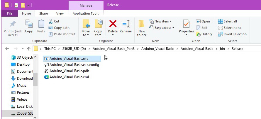
You can find the the compiled exe file inside the project folder:
Arduino_Visual-Basic_Part3\Arduino_Visual-Basic\Arduino_Visual-Basic\bin\Release
Just double click the Arduino_Visual-Basic.exe file to run it
Download
Download the Arduino sketch
Download the Visual Basic project You will need to have Visual Studio installed to use the VB project files.
Next Steps
Play around with the sketch and the Visual Basic app and modify them to do other things.
If you want to know more about sending complex commands or data packets see Arduino Serial: ASCII Data and Using Markers to Separate Data
Things To Improve
The COM port list is created when the app first runs. This means the Arduino has to be on and connected before running the app. What hapens if you open the app before the Arduino? The Ardionos COM port isn’t listed.
A simple way to address this is to add a COM port list refresh button, that, when clicked, calls an “update the COM port list” function.
You could also allow the user to select the serial port properties, such as the baud rate or the parity settings. Just add the necessary drop down lists to the form.
Learn Visual Basic NET
Microsoft – Visual Basic Fundamentals for Absolute Beginners
freecodecamp (youtube) – Learn Visual Basic (.NET) – Full Course
computer Science (youtube) – Visual Basic.NET Programming (21 lessons)
Derek Banas (youtube) – Visual Vasic Tutorial 2017 (don’t worry about the date)
tutlane – Visual Basic (VB) Tutorial
Hi, I am new to Arduino. My Grandson is coming to visit in August, I bought a Edge robotic arm, AT Mega, and two Adafruit motor sheilds. I got the Arm operating ok, I am using an HMI I wrote in VB. I am sending individual numbers to the AT to run the routines, But can only use the single digits 0 – 9, if i try to send the number 10 for instance, the Arduino sees it as a 1 and a 0, then runs the routine assoc with 1 and then with 0. Would you know what I’m doing wrong?
Hi Jim,
Serial data is received one character at a time and you need to store the data somewhere until you have the complete code. This is where the recvWithStartEndMarkers() function comes in. This function copies anything it finds in between the < and > markers to the receivedChars variable.
It would be worth while reading up on serial communications and a good place to start is http://forum.arduino.cc/index.php?topic=288234.0. The function I use is taken directly from this post.
thank you, I’ll check it out.
Hi! Thank you for giving us an idea about our project. But is it possible to replace bluetooth module to rf transceiver module? Does the code works the same?
Hi,
I don’t know which model you have but it is likely that you will need a usb to serial adapter to enable the rf module to talk to a host computer.
Something like http://www.ebay.com/sch/sis.html?_nkw=ft232rl+ftdi+usb+to+ttl+serial+adapter+module+for+arduino+3+3v+5+5v+ftdi232+cg&_itemId=151604208485&_trksid=p2047675.m4096
When you connect the usb/serial adapter to the computer it will be assigned a COM port. Use this instead of the COM port issued to the Arduinio.
Yes, we have usb to serial adapter connected on my laptop but I still can’t connect arduino and vb. I’ve tried your codes but it only shows “Error cannot connect”. I can’t build connection with my arduino. What might be the possible troubleshooting that I need to do?
I would suggest taking a step back and getting the RF modules connected and communicating without using a computer. Get everything working Arduino to Arduino first. This will confirm the modules are working and that you have the right connections.
The code is working right if we connect the arduino directly to our computer but whenever we try to use rf module as our channel of connection, the rf does receive and sends data but can’t reach to arduino. And if I may ask sir, what is the use of your “count” in vb code?
Hi Hakiro,
you need to get the RF module to RF module communication working. The easiest way to do this is by using 2 Arduinos and serial monitors (or something similar) or a basic sketch.
Have a look at https://www.martyncurrey.com/arduino-to-arduino-by-bluetooth/. This uses Bluetooth modules but the principle is the same.
Thank you for a very useful website
It really helped me on the way.
I have copied parts of your code, and found no errors :-)
Hello Martyn,
Big thank u for this example.
Question:
I have add 1 TrackBar and try to control PGA2310 audio volume.
unfortunately i can’t get this working in your code.
Can someone help me with this issue.
Thank u.
The arduino source is working with Rotary encoder:
arduino PGA2310.ino code;
#include
const int PGA_CS_PIN = 11;
const int PGA_SCLK_PIN = 13;
const int PGA_SDI_PIN = 12;
int state, prevstate, volumeLevel, level = 0;
int nextEncoderState[4] = { 2, 0, 3, 1 };
int prevEncoderState[4] = { 1, 3, 0, 2 };
void setup() {
pinMode(PGA_CS_PIN, OUTPUT);
pinMode(PGA_SCLK_PIN, OUTPUT);
pinMode(PGA_SDI_PIN, OUTPUT);
digitalWrite(PGA_CS_PIN, HIGH);
digitalWrite(PGA_SCLK_PIN, HIGH);
digitalWrite(PGA_SDI_PIN, HIGH);
pinMode(5, INPUT);
pinMode(6, OUTPUT);
pinMode(7, INPUT);
digitalWrite(5, HIGH);
digitalWrite(6, LOW);
digitalWrite(7, HIGH);
Serial.begin(9600);
}
void PGA_set_volume(byte value)
{
byte shifted_val = (value << 1);
digitalWrite(PGA_CS_PIN, LOW); // assert CS
SPI_write(shifted_val); // right value (0..255)
SPI_write(shifted_val); // right value (0..255)
digitalWrite(PGA_CS_PIN, HIGH); // deassert CS
}
static inline void SPI_write(byte out_spi_byte)
{
byte i;
// loop thru each of the 8-bits in the byte
for (i = 0; i < 8; i++)
{
// strobe clock
digitalWrite(PGA_SCLK_PIN, LOW);
// send the bit (we look at the high order bit and 'print' that to the remtoe device)
if (0x80 & out_spi_byte) // MSB is set
digitalWrite(PGA_SDI_PIN, HIGH);
else
digitalWrite(PGA_SDI_PIN, LOW);
// unstrobe the clock
digitalWrite(PGA_SCLK_PIN, HIGH);
out_spi_byte <<= 1; // left-shift the byte by 1 bit
}
}
void loop()
{
state = (digitalRead(7) << 1) | digitalRead(5);
if (state != prevstate)
{
if (state == nextEncoderState[prevstate])
{
if (volumeLevel 0)
{
volumeLevel = volumeLevel – 1;
PGA_set_volume(volumeLevel);
Serial.println(volumeLevel, DEC);
}
}
prevstate = state;
}
}
unfortunately I cannot help with the complete code but I would suggest breaking the issue in to small problems.
I presume you are using a PC as a controller, in which case;
Get the controller working with the Arduino. Display the results in the serial monitor.
Get the Arduino to control the PGA2310.
After you have the separate parts working put them together.
If you have not already, I would also suggest joinging the Arduino forum (and possible the EEVBlog forum).
Thanks for the quick response Martyn.
maybe u can have a look shortly this pice of code?.
This part of code i have add in the (your) arduino source:
1, I select the matrix input port first,
2, then i give the PGA command
******************************
// Volume control
if ( receivedChars[3] == ‘1’ && receivedChars[4] == ‘5’ && receivedChars[5] == ‘1’ ) // Volume control 1
{
for ( byte Count = 1; Count 127)
{
volumeLevel = 1 + convertToNumber( 1 );
}
// Set the volume
PGA_set_volume(volumeLevel);
// Serial.println(volumeLevel);
volumeLevel = volumeLevel + 1;
}
}
if (feedback) {
sendOK(151);
}
}
i dont know, but it seems that the some code dissepear.
for ( byte Count = 1; Count <= 15; Count++)
{
connect (0, 0); // Matrix Input 1
update ();
update_required = 0;
}
if ( receivedChars[0] == 'V' )
{
When Copying your code the code says that SerialPort1 is not declared, any solutions?
The serial port object is added through the designer not in the code.
Rather than copying the code, download the complete project.
Great work
please make project using arduino rfid and visual basic
Unfortunately I have not used RFID but I am sure Google will have some answers.
please make project using arduino rfid and visual basic
help please, how can i connect arduino to visual basic with SQl?
DO YOU HAVE VIDEO?
sorry, no video except short demonstrations.
nice job but is too complex for me, i just need to read one value from an arduino, thought the first of your examples was perfect but couldent make it work, i have the microsoft visual studio 2019 ( is the only version available ) .
t
The way you post the your 3rd last example i can open the project folder and it runs , is there any way you can send me the 1rst example in the same way you post the 3rd.?
thanks.
All source code is available for download at the bottom of each post
Nice Posted
Nice post. Is there a way you can explain more about max485 with two or three slaves.