Update: The BLE extension included with the examples is out of date and does not function fully any more. Download the latest version from the app inventer BLE extention download and replace the existing extension. Do not delete the old version, upload the new version and it will over write the older version.
You can check the latest version of the BLE extension on the app inventor BLE page.
Hopefully this guide will give you a good introduction to using the HM-10 with App Inventor 2. I also hope that this takes you beyond the usual starter guides that do not go past very basic information.
Although I am using an Arduino the principles will be the same for any other microprocessor or indeed for using the HM-10 on its own. Warning: This is going to be a very long post.
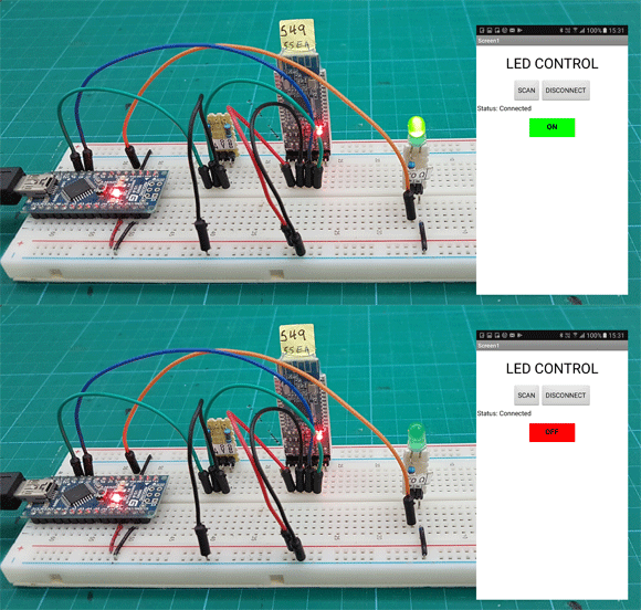
To use this guide you should be somewhat familiar with App Inventor, have a BLE enabled Android device, and of course have an Arduino and a HM-10.
BLE
HM-10
App Inventor 2
Example Project Part 1: Turn an LED on and off basic
Example Project Part 2: Two-way control of an LED
Example Project Part 3: Making the control codes complex
Example Project Part 4: Change how the codes are dealt with
Example Project Part 5: 3 LEDs and 3 switches
BLE
This is a very brief introduction to BLE and no where near the whole story.
BLE is not an upgrade to Bluetooth Classic, it is a different system with different intended uses. BLE works in a very different way to the earlier Bluetooth. BLE is designed for low energy applications and achieves this by using infrequent small packets of data. It is not really designed for continuous connections and large amounts of data. For this, Bluetooth Classic is a better choice. In essence, BLE achieves its low power consumption by not being connected very often, unlike Bluetooth Classic which maintains a constant connection.
There are 2 ways BLE devices can talk to each other; Broadcaster + Observer, and, Central + Peripheral. The HM-10 can use both methods.
- With Broadcaster + Observer there isn’t a standard connection, the Broadcaster, usually some kind of sensor, sends out periodic signals (advertising packets) which the Observer listens for. The Broadcaster does not normally know if anything is listening or not.
- The Central + Peripheral scenario is more like (but not exactly the same) as the classic connection. When the Central (master) device finds a Peripheral (slave) device it wants to connect to it initiates a connection and takes on the master role managing the connection and timings.
Because Bluetooth Classic assumes you are going to use a single connection and the connection is going to be established for a while it does not need to be particular quick at making connections. BLE, on the other hand, is designed to make a lot of short term connections and so is designed to connect and disconnect very quickly.
BLE is all about services and characteristics. A service is a collection of related characteristics and a characteristic is where the data is at. On a typical BLE device you may have a service that contains characteristics dealing with the modules properties such as; the manufacture name, the device name, the firmware ID and/or version number. It may then also have a second service that groups the characteristics that hold the actual data. These may be things like temperature, humidity, brightness. This means, to use BLE, you generally need to know the characteristics you want to use (more specifically the UUIDs for the characteristics).
With BLE the values of these properties are available all the time. If you want to know the manufactures name you read the valve from the manufactures name characteristic. If you want to know the temperature, you read the value from the temperature characteristic. This is very different to how Classic Bluetooth works. With Classic Bluetooth, you only have a single communication channel and all data is sent via the one channel.
Each service and characteristic has a unique identifier called a UUID. This is basically a 24 bit number. In the below HM-10 section, you can see the 2 HM-10 custom characteristic UUIDs; 0000FFE1-0000-1000-8000-00805F9B34FB and 0000FFE2-0000-1000-8000-00805F9B34FB. Sometimes these can be shortened to FFE1 and FFE2.
HM-10
The HM-10 is a low cost serial BLE module made by Jinan Huamao. It has a serial/UART layer which is good and bad depending on what you want to do. The UART layer sits above the BLE layer and makes it very easy to use with the Arduino. For creating simple connections or using with or as a basic iBeacon the HM-10 is ideal, especially for Arduino hobbyists like myself. Unfortunately the UART layer hides the BLE layer from the user and so limits what you can do with it. We are stuck with what BLE functionality Jinan Huamao give us.
While you can create a classic style connection using 2 HM-10s, BLE was not designed for this and if this is all you need then you would be better suited with Bluetooth Classic modules like the HC-05s or a HC-05 and a HC-06. Creating a standard connection with BLE defeats the purpose of BLE and negates many of the benefits of BLE, including the low energy aspects.
For general use, the HM-10 has 2 custom characteristics under a custom service:
CUSTOM SERVICE
• UUID: 0000FFE0-0000-1000-8000-00805F9B34FB
CUSTOM CHARACTERISTICS
• UUID: 0000FFE1-0000-1000-8000-00805F9B34FB
• CUSTOM CHARACTERISTIC
• READ/WRITE/NOTIFY
• UUID: 0000FFE2-0000-1000-8000-00805F9B34FB
• CUSTOM CHARACTERISTIC
• WRITE
Characteristic FFE1 is active by default. FFE2 is non active and has to be turned on before it can be used. Notice that the characteristic FFE2 is write only. This means you can use it to send data to the HM-10 but you cannot use it to send data from the HM-10. In the following examples I will use UUID FFE1 to read and write data.
For more information about the HM-10 see the HM-10 Bluetooth 4 BLE Modules post.
Because of the serial/UART layer and the fact that the HM-10 has limited custom characteristics, I will be using a single characteristic for all data. This means using the HM-10 is not really using BLE as it was intended. If I were do the same thing using a different chip or module that allows more control over the BLE (like the Nordic BLE modules or an Arduino 101) then I would create separate characteristics for the different devices; LEDs would have their own, the switches would have their own. I may, if there weren’t too many, even create separate characteristics for each individual LED or switch. If you want to control just 2 lights having separate characteristics for each light is manageable. If you have many lights, then creating and managing a separate characteristic for each becomes very laborious.
App Inventor 2
App Inventor 2 is a fairly easy way to get in to creating Android apps. It uses the Blockly programming system rather than text and does a lot of the heavy lifting for you. Although it initially may appear simple you can create some surprisingly complex apps with it. AI2 is constantly being developed and updated and one of the latest updates is the new BLE extension. There has been a BLE extension for a while now but this has always been experimental. The new extension hopes to replace the old module with a new more comprehensive and stable system. Note that, at the time of writing, the new BLE extension is still in beta but from my own trials I have found it to work well and be very stable.
To get the most out of this guide you should be a little familiar with App Inventor and how to use the programming blocks. as such I don’t go in to too much detail about App Inventor 2 and if you want to know more start with the App Inventor 2 tutorials.
The new BLE extension is part of AI2 IOT (everything seems to be going IOT) and details about this can be found on the AI2 IOT site. For details about the actual extension and the blocks it has see the BluetoothLE Extension page. The new BLE extension can be downloaded at http://iot.appinventor.mit.edu/assets/resources/edu.mit.appinventor.ble.aix. Please be aware that the extension, although fairly mature, is still in testing and certain things may change.
Note that when you save an aia file the extensions get saved with them. This means you do not need to keep importing the extensions every time you work on an app.
I will be using the BaseConnect aia file as the starting point for the app. This is a bare bones app designed as a template to allow a quick way to scan and connect to BLE devices. The BaseConnect aia file already contains the BLE extension but it may be an older version and you should update the extension before using the app.
App Inventor IOT officially supports the Arduino 101 and the BBC micro:bit, and they have additional support for these boards, but any BLE module, such as the HM-10, can be used.
Example Project Part 1: Turn an LED on and off basic
I start with a very basic app that allows you to control a single LED; turn it on, turn it off. I will then slowly develop this to a robust and extensible system. Something that can be extended and adapted.

First, set up the Arduino and the HM-10
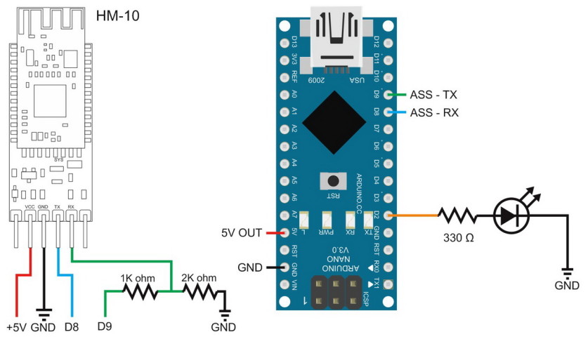
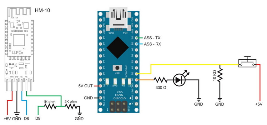
Arduino and HM-10 Circuit 01
A very simple circuit; an Arduino, a HM-10, an LED, and a resistor. The HM-10 is connected to the Arduino’s pins D8 and D9. Pin D2 has a resistor and an LED.
Arduino D8 (AltSoftSerial receive) to HM-10 TX
Arduino D9 (AltSoftSerial transmit) to a voltage divider and then to the HM-10 RX pin
Arduino D2 to a 330 ohm resistor and the LED.
The HM-10 RX pin is 3.3v. The Arduino TX pin is 5V (on my 5V Nano at least). The voltage divider reduces the 5V to 3.3v and stops the world from being destroyed (or at least the RX pin on the HM-10). 5V Arduinos see 3.3v as HIGH so we can connect the HM-10 TX pin directly to the Arduino RX pin without destroying everything.
The voltage divider is made from 2 resistors. A 1K ohm and a 2K ohm.
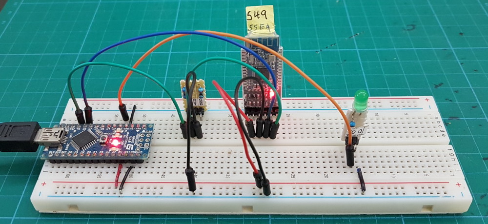
I am using a premade voltage divider and a premade LED that has the resistor built in.
Arduino Sketch
Like the circuit, the sketch is fairly simple. It basically repeats the following;
check for received data,
check the received data for either a “0” or a “1”,
if it finds a “0” then turn the LED off,
if it finds a “1′ then turn the LED on.
The sketch uses AltSoftSerial and this needs to be downloaded and installed before the sketch will compile. On ATmega 328 based Arduinos, such as the Nano, AltSoftSerial uses pins 8 and 9. Other Types of Arduino may have different pins. Check the AltSoftSerial pages for details.
// Arduino, HM-10, App Inventor 2 // // Example Project Part 1: Turn an LED on and off basic // By Martyn Currey. www.martyncurrey.com // // Pins // BT VCC to Arduino 5V out. // BT GND to GND // Arduino D8 (ASS RX) - BT TX no need voltage divider // Arduino D9 (ASS TX) - BT RX through a voltage divider // Arduino D2 - Resistor + LED // https://www.pjrc.com/teensy/td_libs_AltSoftSerial.html #include <AltSoftSerial.h> AltSoftSerial ASSserial; byte LEDPin = 2; char c=' '; void setup() { Serial.begin(9600); Serial.print("Sketch: "); Serial.println(__FILE__); Serial.print("Uploaded: "); Serial.println(__DATE__); Serial.println(" "); ASSserial.begin(9600); Serial.println("ASSserial started at 9600"); Serial.println(" "); pinMode(LEDPin, OUTPUT); } void loop() { // Read from the Bluetooth module and turn the LED on and off if (ASSserial.available()) { c = ASSserial.read(); Serial.println(c); // The ascii code for 0 is dec 48 // The ascii code for 1 is dec 49 if ( c== 48) { digitalWrite(LEDPin, LOW); } if ( c== 49) { digitalWrite(LEDPin, HIGH); } } } |
This is a very simple sketch. It checks for serial data and if any is available it checks for a “0” or a “1”. If there is a “0” or a “1” the LED is turned on or off accordingly. Any other characters are ignored.
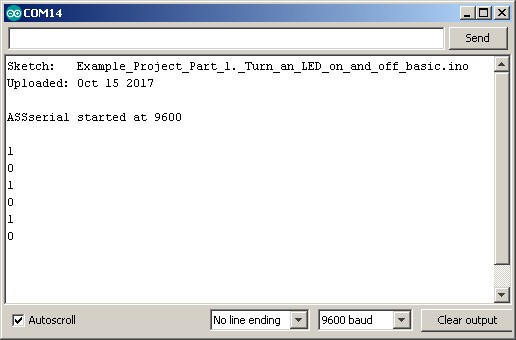
You can check that the sketch works by opening up the serial monitor. Whatever is received from the HM-10 is displayed in the serial monitor.
Android App
We start with a very simple app that will send 2 control codes; “0” and “1”. The “0” is the code to turn the LED off and the “1” is the code to turn the LED on. This means the app requires some way to send the codes and the Arduino requires a way to receive and detect them. The initial app is dumb in that it does not know the actual state of the LED, it simply sends the codes when the user clicks the buttons. More advanced features will be added later.
To make life a little easier I am starting with the BaseConnect template created by the AI2 team. The BaseConnect aia file is the bare bones necessary to scan for and connect to BLE devices. There are a couple of issues with it (like the size of the text in the device list) but it is a good place to start. When developing BLE apps you do not need to use the BaseConnect file but should be used as a reference if you are just starting with BLE on AI2.
You can download the BaseConnect template from http://iot.appinventor.mit.edu/assets/resources/IoT_BaseConnect.aia. I doubt it will change but if you want to be sure you are using the same version as me you can download from here.
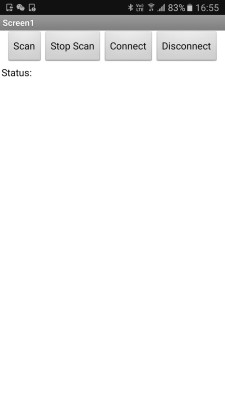
Open App Inventer, upload the BaseConnect aia file and save it as “ARD_HM10_AI2_Single_LED_01”. If you have an Android device and the HM-10 available connect using the MIT AI2 Companion app and give it a try.
Click Scan and see what you can find.
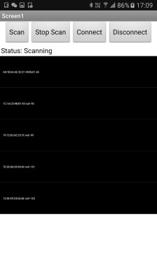
Here the app has found various BLE devices including a HM-10. Unfortunately the text is too small see them.
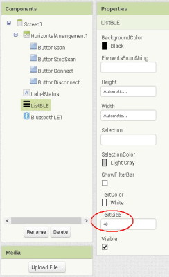
In the designer, select ListBLE and change the TextSize to 48. We can now read the names of the found BLE devices.
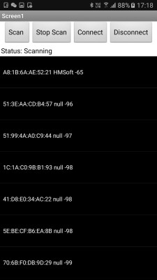
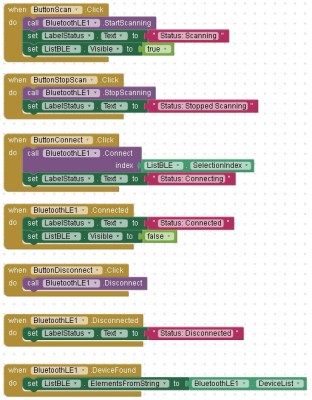
The BaseConnect app is very basic and in the Blocks section we can see that it contains only 7 blocks or procedures. What each procedure does should be self explanatory.
Add the LED controls buttons
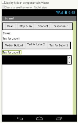
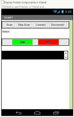
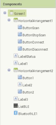
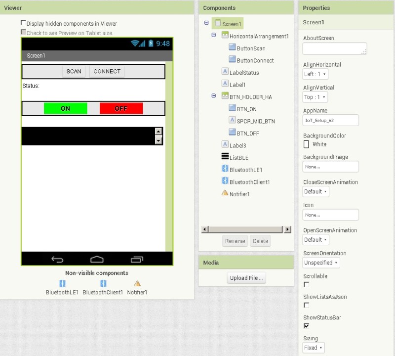
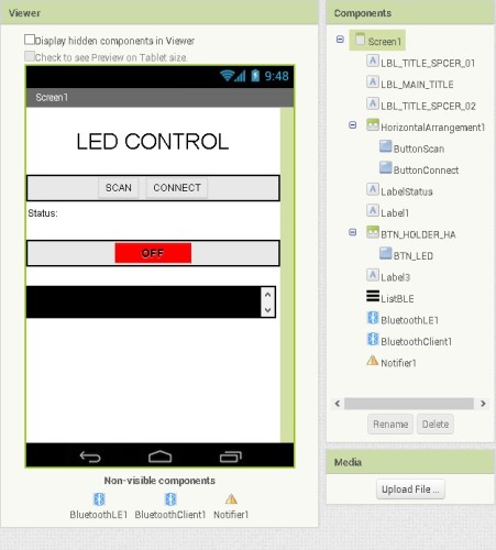
Next is to add the controls to turn the LED on and of. For this I am using a couple of buttons. Along with the buttons I am using some text labels that are used as spacers. The buttons are inside an Horizontal Arrangement.
Download ARD_HM10_AI2_Single_LED_01.aia
Once you have added the controls save as ARD_HM10_AI2_Single_LED_02
We now need to add the functions to send the control codes. This is not as straight forward as you may expect, especially if you have used Bluetooth Classic. With Bluetooth Classic, once you have made a connection you simply write the data to the connection channel. With BLE you need to write the data to a specific characteristic and this means you need to know the correct UUID for that characteristic and also the UUID for the service the characteristic is under. With BLE we no longer have a connection channel we have characteristics.
In this example I am using the default HM-10 custom characteristic 0000FFE1-0000-1000-8000-00805F9B34FB which is under the custom service 0000FFE0-0000-1000-8000-00805F9B34FB.
The AI2 BLE extension allows us to write various types of data and for this example we could use bytes or strings, since I am using “0” and “1” I could use either. I am going with strings so that using more complex control codes in the future will require less changes.
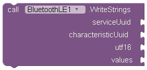
The BLE Write blocks normally expect the data to be in a list. Fortunately, if you use plain data as I do below, AI2 will convert it for you.
You can see, to be able to write data we need the service UUID and the characteristic UUID.
The WriteStrings function is blind in that it just sends the data and it has no idea if the HM-10 ever receives it. In the BLE extension we can check for a completed transmission by using the WriteStringsWithResponse block.
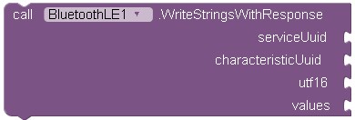
This instructs the HM-10 to send back an acknowledgement. AI2 gets the acknowledgement and this triggers an event in AI2 that we can check. For now we do not need this so I am just using the WriteStrings function.
In the Blocks editor, add a couple of global variables to hold the UUID numbers and add the button click event blocks for the LED control buttons:
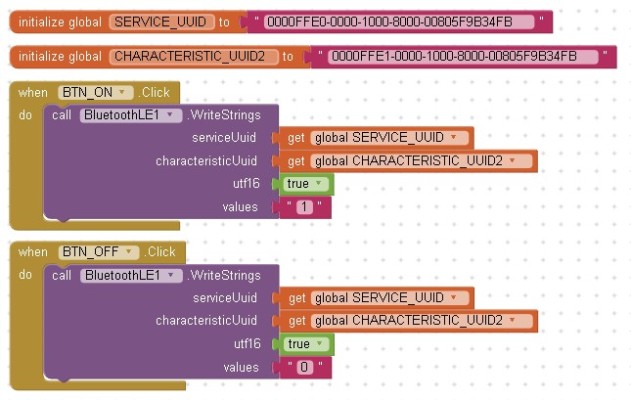
You should be able to work out that, when the ON button is clicked the code sends a “1” and when the OFF button is clicked it sends a “0”.
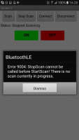
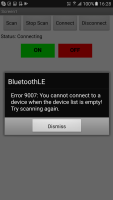
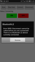
Open up the companion app and give it a go. It works, sort of, as long as your Android device has Bluetooth enabled and you connect to the HM-10 before you click one of the LED control buttons. If you try to scan while Bluetooth is turned off you get a system error. If you click one of the LED control buttons before making a connection you get a system error.
If you try to scan when Bluetooth is disabled you get a system error message and then the Android asks if you want to enable Bluetooth. At present there isn’t a clean way to check if Bluetooth is enabled using the BLE extension. There is a way with Bluetooth Classic. So as a work around we can add the Bluetooth Classic client and then check to see if Bluetooth is enabled. If Bluetooth is not enabled we can issue our own message with a notifier.
Download ARD_HM10_AI2_Single_LED_02.aia
Save the app as ARD_HM10_AI2_Single_LED_03 before moving on.
Add the Bluetooth Client and then add a notifier:
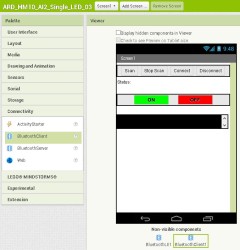
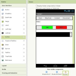
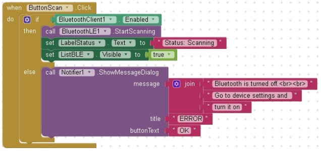
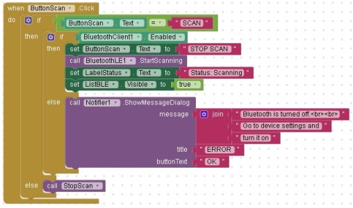
We now need to change what happens when the Scan button is clicked. When the button is clicked we want to first check to see if Bluetooth is enabled, if it is we can scan. If it is not we want to issue an error message. We check to see if Bluetooth is enable with the BluetoothClient.Enabled block.
In the Blocks editor add a check for Bluetooth to the ButtonScan.Click procedure. At the same time add an else to the if/then block and a call to the notifier. The call to the notifier displays the error message when Bluetooth is not enabled.
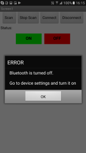
Now if we try to scan before Bluetooth is turned on we get a warning:
With the LED control buttons, we need to check to see if we are connected before trying to send the control codes. We can do this with the BLE isDeviceConnected block.
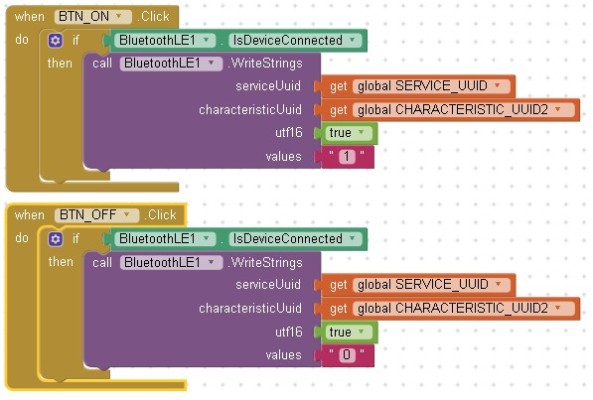
Now if you click the ON or OFF button when the HM-10 is not connected nothing happens. You could, if you wish, have an error message displayed but you will find you can get a lot of error messages and they quickly become annoying, therefore, I find it better to simply not do anything. Or, you could make the buttons inactive until a connection is made. I leave that for you to do.
Give the app another try. It should be better. When Bluetooth is not enabled we get a nice message telling us to turn it on. When we click the LED control buttons without a connection we no longer get the system error message. What happens if we click the other buttons? We get more system error messages.
We could add more checks but a better way (to me at least) is to use toggle buttons.
At the moment we have one button to start a scan and one button to stop the scan. These can be combined in to one toggle button; SCAN and STOP SCAN. The app will start with the button showing SCAN and when it is clicked, if Bluetooth is enabled, the scan will start and the button changes to STOP SCAN. This means the user can only press the STOP SCAN button if they have already pressed the SCAN button. This method also means the button text can be used as a kind of status flag. We can then do the same with the Connect and Disconnect buttons.
In the designer I changed the Scan button text to SCAN and deleted the Stop Scan button. In the blocks editor I deleted the ButtonStopScan.Click event function. We no longer need it.

I extended the ButtonScan.Click event procedure:
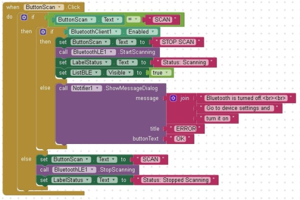
Now the function first checks the button text and if the text is “SCAN” we know we need to start a scan. If the text is not “SCAN” it must be “STOP SCAN” so we stop the scan.
Now do the same for the Connect and Disconnect buttons. Combining the two buttons in to one toggle button will mean the user can only disconnect when there is an active connection but it will not stop the user clicking the Connect button before they have selected a device to connect to. We can look at this after we have combined the buttons.
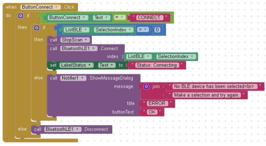
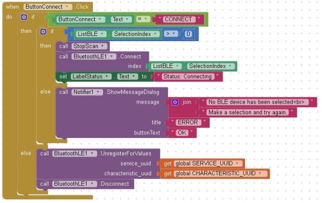
To the ButtonConnect.Click event function add a check to see what button text is displayed and move the disconnect instructions:
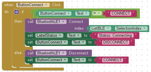
In the Blocks editor, delete the ButtonDisconnect.Click event function and then delete the ButtonDisconnect button in the Designer. On the ButtonConnect button change the text to be “CONNECT”.
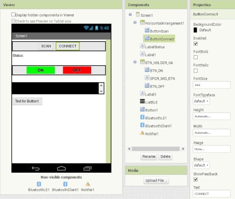
If you give the app a try you should find the connect and disconnect works but you still have the system errors if you try to connect before scanning and selecting a device. Let’s fix that next.
The AI2 ListView element has a couple of properties we can use to determine if one of the list elements has been selected; List.Selection and List.SelectionIndex. Before a selection is made SelectionIndex is 0 and List.Selection is null or “”. Using SelectionIndex we can simply see if SelectionIndex is greater than 0 to see if the user has selected something.
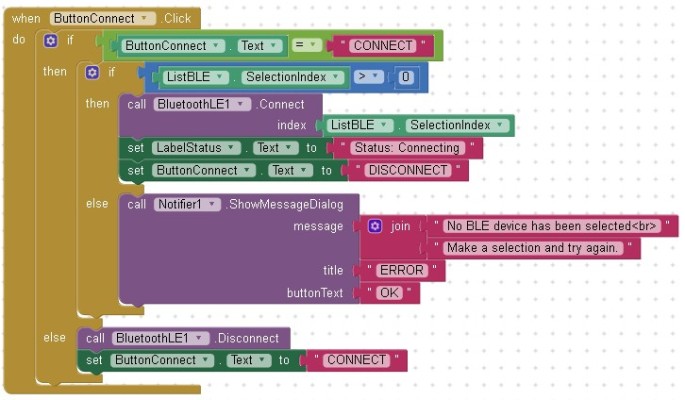
Give it a try. It should work. At least it works the first time you try to connect. What happens if you scan, connect and then disconnect and then connect again without scanning. The app will try to connect to the same device again. The app remembers which item in the list you selected and uses it again. You can either leave this as the standard behaviour or you can reset the list index when a connection is made. I will leave it, there are other things I want to fix.
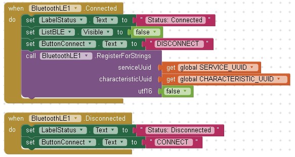
At the moment, when the user clicks the CONNECT/DISCONNECT button the button text changes straight away. It changes even when there is a problem and the connection is not successful. To correct this, move the instructions to change the button text to the BluetoothLE1.Connected and BluetoothLE1.Disonnected functions. You should now have something like the following:
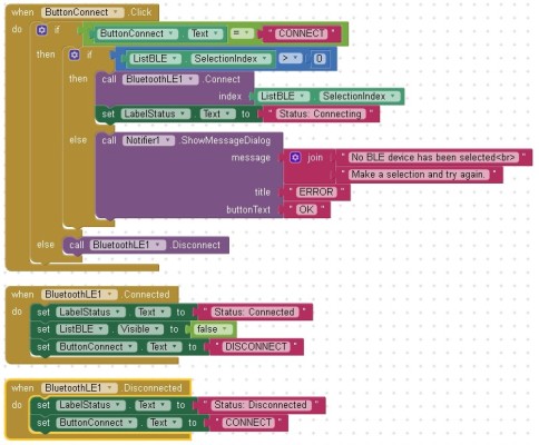
In the ButtonConect.Click event function there is an instruction to set the LabelStatus to “Status: Connecting”, we could do the same with the CONNECT/DISCONNECT button. I leave for you to implement if you so wish.
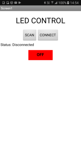
We now have an app that looks like this. It is starting to look a little cleaner and leaner.
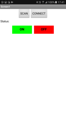
Download ARD_HM10_AI2_Single_LED_03.aia
Save this as ARD_HM10_AI2_Single_LED_04
The next step, of course, is to combine the LED control buttons into one toggle button that says either “ON” or “OFF”.
To combine the LED control buttons in to one toggle button we use exactly the same method as above. We have one button and when clicked we check the button text. If it says “ON” we know the LED is on and we need to turn it off. If it is not “ON” then is must be (should be) “OFF” so the LED is off and we need to turn it on.
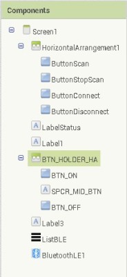
We will use the on button and rename it to BTN_LED.
One thing to notice is that the LED button will now reflect the LED status not the command. This means the controls being sent are reversed. In the previous code, the ON button was used to turn the LED on. Now, if the button says “ON” it means the LED is on and it needs turning off.
We can now delete the OFF button and the button spacer:
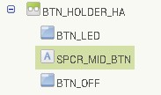
After adding the if/then condition statement to check the button text and moving the blocks we have:
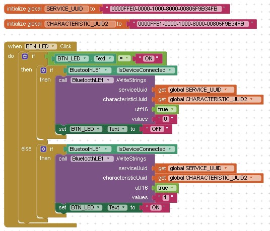
This works fine. The on/off button now fully controls the LED. There are still a couple of things to correct.
1. When the app first starts the button says “ON” and the LED is normally off at the beginning.
2. The button doesn’t change colour.
3. We don’t need to check for a connection in 2 places.
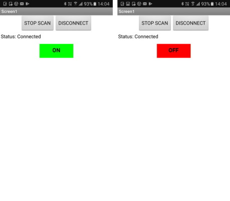
In the Designer change the button text to “OFF” and the button back ground colour to red. Now when it starts the default text will be OFF.
To change the button colour we use the button BackgroundColor property. The colours are grabbed from the Color menu.

AI2 has far more colour options but for this example I am using the basic colours from the colour menu.
Here we are with the colour commands. The button now shows green when the LED is on and red for when it is off.
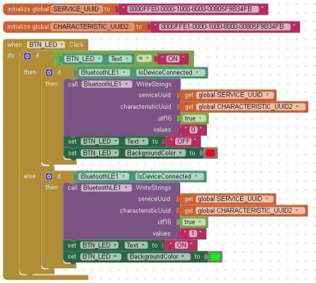
Rather than checking for a connection after checking the button text, we can check for a connection first. In this way we only need to have the check once. For this we just need to move one of the if/thens above the button text checks.
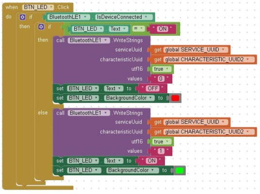
The app works the same but the code is a little better.
There is something else I want to look at. When you click the SCAN button, the app keeps scanning until you click the STOP SCAN button. When you make a connection, the app continues to scan and it does not need to. To change this, let’s make it so that when we click the CONNECT button we stop the scanning at the same time.
If we look at the SCAN button function
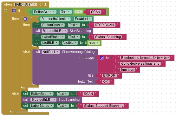
If the button text is not equal to “SCAN” it must be “STOP SCAN” and to stop scanning the app processes the statements at the bottom.

We could simple duplicate these statements in the CONNECT button function but a better way is to move these statements in to their own procedure and call the procedure.
Grab a new procedure block and move the stop scan blocks to it. Rename the new procedure to StopScan.

After a new procedure has been created it is added to the procedure menu:
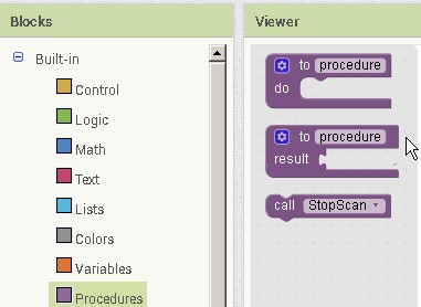
We now have the call StopScan procedure block. Drag this out and put it in the ButtonScan. Click procedure.
To stop scanning when the CONNECT button is clicked, add the StopScan procedure call to the ButtonConnect.Click procedure in the CONNECT section after the ListBLE SecitionIndex check.
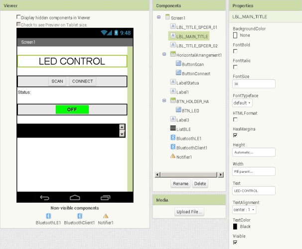
One last thing I want to do, add a title to the app. In the designer, add 3 labels to the very top of the screen.
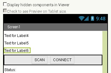
rename to
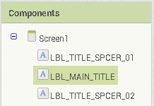
Edit the spacers:
Height = 10 pixels
Width = Fill Parent
Text = “”
Edit the title:
Height = automatic
Width = Fill Parent
Text Alignment = center
Text = “LED CONTROL”
FontSize = 30.
That’s about it for the first part. We have an app that can control an LED via a remote connection with an HM-10.
Download ARD_HM10_AI2_Single_LED_04.aia
In part 2 I add a button switch on the Arduino and have 2 way control.
Example Project Part 2: Two-way control of an LED
In this part we add a switch on the Arduino side so that we can control the LED by a physical switch as well as from the app. The button switch will act as a toggle switch (same as the button in the app) and control the LED locally. This means, on the Arduino, we need add code that;
– checks the switch, and
– if the switch is pressed change the state of the LED
– let the app know when the LED has changed.
We let the app know by sending the control codes to the app from the Arduino. Same as before; “0” for off and “1” for on.
In the app we will need to check for incoming data and if the data is a “0” or “1” set the LED control button accordingly.
Circuit
To the circuit, add a button switch + pull down resistor to pin D3.
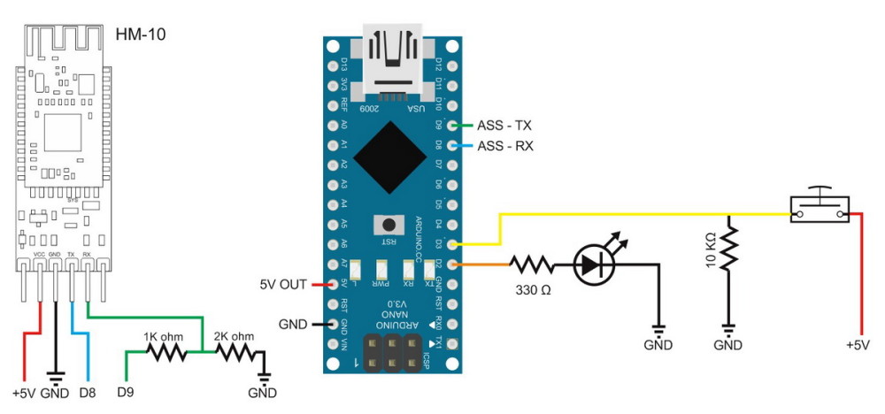
Arduino Sketch. Example Project Part 2: Turn an LED on and off 2way control
Now that we have a button switch we need to check it. The code for this is inside its own function called checkSwitch() which we call from the main loop. checkSwitch() checks to see if the switch has been pressed and if so changes the LED, at the same time it sends the appropriate control code to the app via the serial connection to the HM-10.
The code that checks the received serial data is the same as before but this has also been moved to its own function called checkRecievedData().
Using functions like this keeps the code in the main loop clean and tidy. It also means it is easier to reuse the same code.
// Arduino, HM-10, App Inventor 2 // // Example Project Part 2: Turn an LED on and off 2 way control 01 // By Martyn Currey. www.martyncurrey.com // // Pins // BT VCC to Arduino 5V out. // BT GND to GND // Arduino D8 (ASS RX) - BT TX no need voltage divider // Arduino D9 (ASS TX) - BT RX through a voltage divider // Arduino D2 - Resistor + LED // Arduino D3 - 10K pull down resistor + button switch // AltSoftSerial uses D9 for TX and D8 for RX. While using AltSoftSerial D10 cannot be used for PWM. // Remember to use a voltage divider on the Arduino TX pin / Bluetooth RX pin // Download from https://www.pjrc.com/teensy/td_libs_AltSoftSerial.html #include <AltSoftSerial.h> AltSoftSerial ASSserial; // Constants for hardware const byte LEDPin = 2; const byte SwitchPin = 3; // general variables boolean LED_State = false; boolean switch_State = false; boolean oldswitch_State = false; char c=' '; void setup() { Serial.begin(9600); Serial.print("Sketch: "); Serial.println(__FILE__); Serial.print("Uploaded: "); Serial.println(__DATE__); Serial.println(" "); ASSserial.begin(9600); Serial.println("AltSoftSerial started at 9600"); Serial.println(" "); pinMode(LEDPin, OUTPUT); digitalWrite(LEDPin,LOW); pinMode(SwitchPin, INPUT); } // void setup() void loop() { checkSwitch(); checkRecievedData(); } void checkSwitch() { // Simple toggle switch function with even simpler debounce. boolean state1 = digitalRead(SwitchPin); delay(1); boolean state2 = digitalRead(SwitchPin); delay(1); boolean state3 = digitalRead(SwitchPin); if ((state1 == state2) && (state1==state3)) { switch_State = state1; if ( (switch_State == HIGH) && (oldswitch_State == LOW) ) { // toggle LED_State. LED_State = ! LED_State; // If LED_State is HIGH then LED needs to be turned on. if ( LED_State == HIGH) { digitalWrite(LEDPin,HIGH); // turn on the LED ASSserial.print("1" ); // tell the app the LED is now on Serial.println("Sent - 1"); } else { digitalWrite(LEDPin,LOW); // turn off the LED ASSserial.print("0"); // tell the app the LED is now off Serial.println("Sent - 0"); } } oldswitch_State = switch_State; } } void checkRecievedData() { // Read from the Bluetooth module and turn the LED on and off if (ASSserial.available()) { c = ASSserial.read(); Serial.println(c); // The ascii code for 0 is dec 48 // The ascii code for 1 is dec 49 if ( c== 48) { digitalWrite(LEDPin, LOW); LED_State = LOW; } if ( c== 49) { digitalWrite(LEDPin, HIGH); LED_State = HIGH; } } } |
Updating the app
Before continuing, save the previous work as ARD_HM10_AI2_Single_LED_05
At the moment the app can only send control codes, it cannot receive them. We now need to give the app the ability to receive data.
To receive data from BLE devices there a few of things we need to know.
– The service UUID
– The characteristic UUID
– The data type (byte, string, integer, float, short, long)
We are using the default custom service and characteristic on the HM-10 so we know the UUIDs. We are using strings, so we know the data type.
The BLE extension has various blocks for receiving different kinds of data, since we are using strings we use the .StringsReceived block

We cannot use the .StringsReceived block on its own. It relies on a data received event that is created with the .RegisterForStrings block

Note that this is turn relies on the characteristic having a notify property. Behind the scenes AI2 tells the BLE module to turn on notifications and then uses the notifications to generate the data received event.
When we are finished with the connection it is good practice to unregister or cancel the data received event and this is done with the .UnregisterForValues block

We cannot register before we have a connection so a good place to have the .RegisterForStrings block is inside the BluetoothLE1.Connected procedure. Then, after a connection is established the .RegisterForStrings block is called straight away.
The .UnregisterForValues block should be called before the call to disconnect. If you try to .UnregisterForValues after the connection has been broken you will get an error.
The new app has 2 possible ways to change the LED control button;
1 – by clicking the button,
2 – by the control code.
This means we have 2 parts of the app that can change the button to “ON” and 2 parts that can change the button to “OFF”. Rather than duplicate the same code I have moved the blocks that change the LED button properties to their own procedures
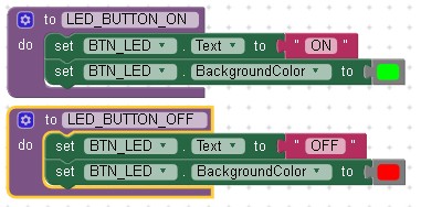
Now, to change the button we simply call LED_BUTTON_ON or LED_BUTTON_OFF. In the BTN_LED.Click event procedure I have replaced the blocks with a call to the appropriate procedure.
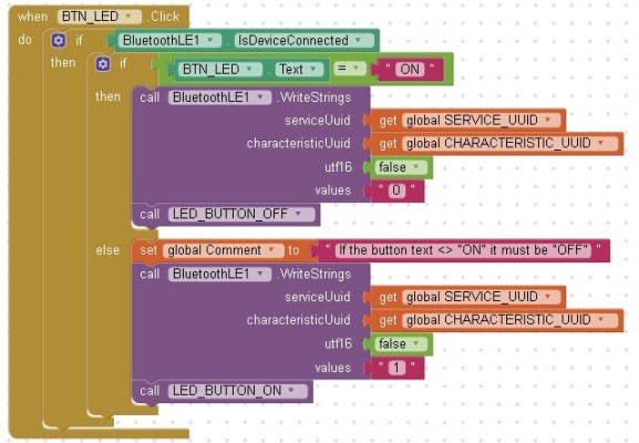
All that is left is to check for received data and update the LED control button if required.
As mentioned earlier, the .StringsReceived block is called when new data is received.

This gives us a list rather than plain data so we need to process the list. First, double check that we actually have a list with the “is a list?” block.
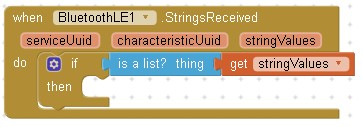
then loop through all items in the list with the “for each item in list” block. The list is the stringValues.
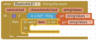
We should only have 1 character and so only have one element in the list and you may feel that we do not need to loop through all elements. For this simple example we probably don’t but it is good practice and later you may have an app that receives a lot of data very quickly and you will then need to do this. Also, what happens if somebody presses the button really quickly?
Now we need to add the check to see if the data is a “1” or a “0” and if it is change the LED control button.
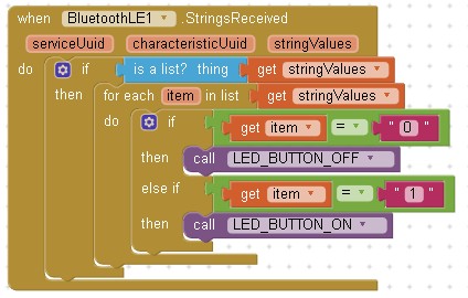
You should notice that I use 2 if statements rather than 1 if/then. The above checks for a “0” and then checks for a “1”. Doing it like this means incorrect characters are ignored.
And that’s it. We now have 2 way control.
Download ARD_HM10_AI2_Single_LED_05.aia
Download Arduino Sketch. Example Project Part 2: Turn an LED on and off 2way control
If all you want to do is turn things on and off this method works well and you can expand it by using additional single character codes:
0 & 1 – LED 1 on/off
2 & 3 – LED 2 on/off
4 & 5 – Lights on/off
6 & 7 –
8 & 9 –
After you run out of numbers use letters, there are many and this method will allow you to control a lot of LEDS, or lights, or buzzers, or locks, etc.
What if you want to control something that does not have a simple on/off status or send data that is not simple binary. In the next part I look at expanding the control codes beyond the simple “0” and “1” so that we can then expand what we can control.
Example Project Part 3: Making the control codes complex
In part 3, all we do is change the control codes. We make them more complex. The function of the app and sketch remains the same and the LED is turned on and off in exactly the same way but we do it in a more complex way.
Although this may seem like a waste, changing the control codes will allow us to add more complex operations; like dimming an LED or controlling an RGB LED.
The new control codes
Instead of the single character codes used previously, multi character codes will now be used. For the LED we will have a 3 character codes; “L10” and “L11”.
L10 – L for LED, 1 for LED #1, and 0 for off
L11 – L for LED, 1 for LED #1, and 1 for on
Once we have the code to accommodate 1 LED, you should be able to see, that to add a second LED we simply use “L20” and “L21”. For a third LED we would use “L30” and “L31”.
Using multi character codes is not so straight forward though. We need to check all the characters in the code, not just one. Is this a code for LEDs, which LED, is it on or off? We have another problem. When using serial communications you cannot guarantee you will get all the data in one go. It is very possible that the codes arrive in pieces. “L” followed by “11” or “L1” followed bu “0”. This is true for both the app and the Arduino and means we need a way to tell we have the whole code. There are many ways of doing this. My preferred method, for use with ascii, is to use start and end markers. Start and end markers means we enclose the data in start and end markers. We then keep receiving data until we have both markers, at which point we know we have a complete code. In the below example I use “[” and “]”.
On the Arduino side (controls to the Arduino) I will be using fixed length codes; “[L10]” and “[L11]”. On the AI2 side I will use comma separated data “[L,1,0]” and “[L,1,1]”. AI2 has better data manipulation functions and we can directly transfer a variable that contains commas to a a list of separated values. (You can do this with any character not just commas).
In the Arduino sketch I am using Robins2’s recvWithStartEndMarkers() function. This function is part of a very good post on the Arduino forum. All I have done is change the start and end characters to “[” and “]”. If you want to learn more about using serial on the Arduino, this post is a good place to start.
In the app I have created a Blockly version of the recvWithStartEndMarkers() function. It is not exactly the same but it does a similar thing.
Circuit
The circuit is exactly the same as before. One LED and one button switch connected to an Arduino.
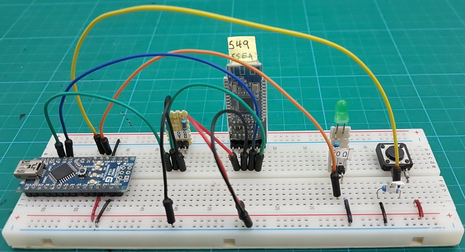
Arduino Sketch. Example Project Part 3: Complex control codes
There are few things to note about the new sketch. We now have new variables that help handle incoming data; maxDataLength, receivedChars[], and, newCommand.
maxDataLength is used to store the maximum length of the the incoming data. This means commands cannot be longer than the value of maxDataLength.
receivedChars[] stores the complete received command
newCommand is a flag used to tell the sketch if there is a new command or not.
A new function, recvWithStartEndMarkers(), has been added. This checks the incoming data for the start and end markers and then copies any valid data if finds in to the receivedChars[] char array.
Inside the processCommand() function, the received command is checked. If it is a valid command action is taken.
if (strcmp (“L10”,receivedChars) == 0)
if (strcmp (“L11”,receivedChars) == 0)
This may not be the best way to do this. After all if we are checking “L10” and “L11” as single entities we might as well have stayed with “1” and “0”. I will address this is part 4.
You should note that the codes being sent from the Arduino have a slightly different format to the ones it is receiving.
// Arduino, HM-10, App Inventor 2 // // Example Project Part 3: Complex control codes // By Martyn Currey. www.martyncurrey.com // // Pins // BT VCC to Arduino 5V out. // BT GND to GND // Arduino D8 (ASS RX) - BT TX no need voltage divider // Arduino D9 (ASS TX) - BT RX through a voltage divider // Arduino D2 - Resistor + LED // Arduino D3 - 10K pull down resistor + button switch // AltSoftSerial uses D9 for TX and D8 for RX. While using AltSoftSerial D10 cannot be used for PWM. // Remember to use a voltage divider on the Arduino TX pin / Bluetooth RX pin // Download from https://www.pjrc.com/teensy/td_libs_AltSoftSerial.html #include <AltSoftSerial.h> AltSoftSerial ASSserial; // Variables used for incoming data const byte maxDataLength = 20; char receivedChars[21] ; boolean newCommand = false; // Constants for hardware const byte LEDPin = 2; const byte SwitchPin = 3; // general variables boolean LED_State = false; boolean switch_State = false; boolean oldswitch_State = false; void setup() { Serial.begin(9600); Serial.print("Sketch: "); Serial.println(__FILE__); Serial.print("Uploaded: "); Serial.println(__DATE__); Serial.println(" "); ASSserial.begin(9600); Serial.println("AltSoftSerial started at 9600"); Serial.println(" "); pinMode(LEDPin, OUTPUT); digitalWrite(LEDPin,LOW); pinMode(SwitchPin, INPUT); } // void setup() void loop() { checkSwitch(); recvWithStartEndMarkers(); // check to see if we have received any new commands if (newCommand) { processCommand(); } // if we have a new command do something about it } /* **************************************** * Function checkSwitch() * checks the status of a button switch and turns an LED on or off depending on the switch status * * passed: * * global: * switch1_State * LED1_State * oldswitch1_State * * Returns: * * Sets: * switch1_State * LED1_State * oldswitch1_State */ void checkSwitch() { // Simple toggle switch function with even simpler debounce. boolean state1 = digitalRead(SwitchPin); delay(1); boolean state2 = digitalRead(SwitchPin); delay(1); boolean state3 = digitalRead(SwitchPin); if ((state1 == state2) && (state1==state3)) { switch_State = state1; if ( (switch_State == HIGH) && (oldswitch_State == LOW) ) { LED_State = ! LED_State; if ( LED_State == HIGH) { ASSserial.print("[L,1,1]" ); digitalWrite(LEDPin,HIGH); Serial.println("Sent - [L,1,1]"); } else { ASSserial.print("[L,1,0]"); digitalWrite(LEDPin,LOW); Serial.println("Sent - [L,1,0]"); } } oldswitch_State = switch_State; } } /* **************************************** * Function processCommand * parses data commands contained in receivedChars[] * receivedChars[] has not been checked for errors * * passed: * * global: * receivedChars[] * newData * * Returns: * * Sets: * receivedChars[] * newData */ void processCommand() { if (strcmp ("L10",receivedChars) == 0) { digitalWrite(LEDPin,LOW); LED_State = LOW; Serial.println("LED1 LOW"); } else if (strcmp ("L11",receivedChars) == 0) { digitalWrite(LEDPin,HIGH); LED_State = HIGH; Serial.println("LED1 HIGH"); } receivedChars[0] = '\0'; newCommand = false; } // function recvWithStartEndMarkers by Robin2 of the Arduino forums // See http://forum.arduino.cc/index.php?topic=288234.0 /* **************************************** * Function recvWithStartEndMarkers * reads serial data and returns the content between a start marker and an end marker. * * passed: * * global: * receivedChars[] * newData * * Returns: * * Sets: * newData * receivedChars * */ void recvWithStartEndMarkers() { static boolean recvInProgress = false; static byte ndx = 0; char startMarker = '['; char endMarker = ']'; char rc; if (ASSserial.available() > 0) { rc = ASSserial.read(); if (recvInProgress == true) { if (rc != endMarker) { receivedChars[ndx] = rc; ndx++; if (ndx > maxDataLength) { ndx = maxDataLength; } } else { receivedChars[ndx] = '\0'; // terminate the string recvInProgress = false; ndx = 0; newCommand = true; } } else if (rc == startMarker) { recvInProgress = true; } } } |
Updating the app
Before proceeding, save the previous aia file as ARD_HM10_AI2_Single_LED_06
To see if the Arduino sketch works, in the BTN_LED.Click procedure, change the codes sent from the app to “[L10]” and “[L11]”
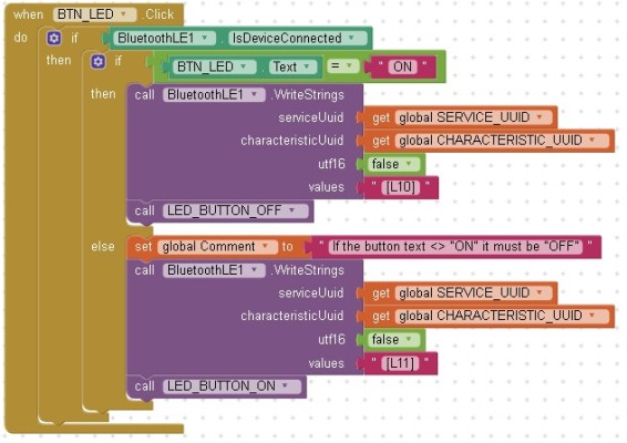
If you load up the companion app and give it a try you should find the app can control the LED but when the button switch is pressed the LED control button in the app does not change. This is because the Arduino is sending the new control codes and the app does not yet know about them. Let’s change that.
In the previous version of the app, the app only had to deal with single characters and receiving these and checking them is fairly simple. Now we have more than one character and, like the Arduino sketch, we need a way to get all the data together and ensure we have a complete command.
In the Arduino sketch, the receivedChars variable was used to store the received data. In the app we will use something similar, a global variable called BT_receivedData_Buffer
![]()
and when we get new data we add it to the buffer. In the BluetoothLE1.StringsReceived procedure, remove the blocks that check for a “1” and a “0” and replace with

This should give you

Now whenever new data is received it is added to the buffer rather than being acted upon straight away. Of course, this means we now need to do something with the buffer.
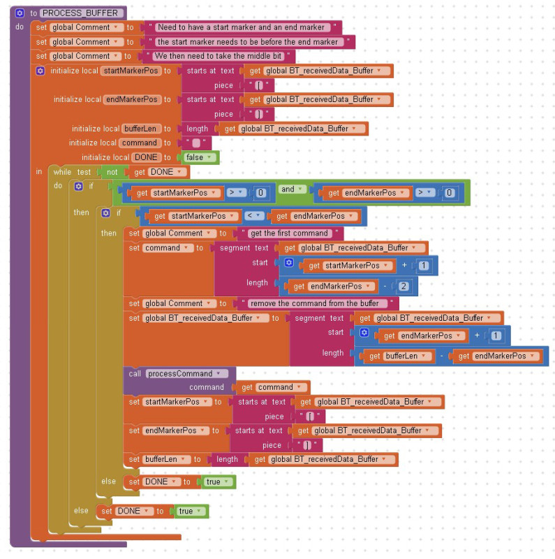
To handle the buffer create (drag from the menu) a new procedure and rename it to PROCESS_BUFFER. At this point it might be a good idea to think about what we have and what we want to do.
We have a variable that may or may not contain a control code. We know that a complete code will be sandwiched between the start and end markers so we can use these to determine is we have a complete code. If the buffer contains a start marker “[” and we have a end marker “]” and the start marker is before the end marker there is a good chance we have a code. We then take that code and see if it is one we want. If it is, we do something.
Rather than trying to step through this process one block at a time I will show my solution and then try to explain how it works.
First, local or temporary variables are created

As the local variables are created the values of startMarkerPos and endMarkerPos are set. If the marker character is not found startMarkerPos and/or endMarkerPos will be 0.
Next, the position of the markers is checked. If the markers are found their positions will be > 0, the next check confirms that the start marker is before the end marker.

After this, the actual command is copied to the command local variable.

and then the command (including the start and end markers) is removed from the buffer

At this point the variable command stores a command which is sent to the processCommand procedure. We haven’t created this yet.
Finally, there is a check to see if there are any more start and end markers and if so the whole process is repeated.
All this is contained in a while loop. In the form while not done, keep going.
![]()
This is one of my preferred ways of looping when there is more than one condition used to exit the loop. I use a variable called Done, set this to false at the start and then, when finished set it to true to drop out of the loop. I then get “while not done”. which is easy to read and, to me at least, makes sense. I suspose you could also used while not finished, and if you swaped the polarity, while thereIsSomethingLeftToDo.
We then need to call the PROCESS_BUFFER procedure so we add a call in the BluetoothLE1.StringsReceived function

All this will work well as long as the start marker is always before the end marker. What happens if we get an end marker first. The app will never progress. It will find both markers but the start marker will not be first so it drops out of the loop. Next time the buffer is checked it will have exactly the same result.
To stop this happening I add a trim to start marker function. This trims the buffer so that the first character will be a start marker (as long as there is one).

And the call to TrimToStartMarker is placed at the beginning of the PROCESS_BUFFER procedure.

All that is left to do is check the code is valid and change the LED control button. Here is the PROCESS_COMMAND procedure.
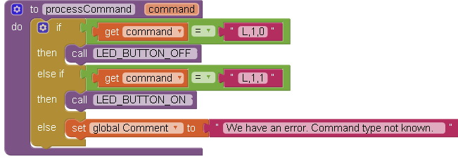
Here what the blocks look like now

Download ARD_HM10_AI2_Single_LED_06.aia
Download Arduino Sketch. Example Project Part 3: Complex control codes
In part 4 we change how the control codes are dealt with, should be short and simple. In part 5 we add more LEDs and switches. In part 6 we try sliders and control the brightness of an LED. Stay tuned.
Example Project Part 4: Change how the codes are dealt with
In this section we start to prepare for additional devices such as more LEDs.
At the moment, the control codes are checked as single entities, for example “L10” and “L11”. Here we break the codes in to separate parts or characters and deal with each character separately:
L for LED
1 for LED number
1/0 for on or off.
If all you want to do is switch 2 or 3 things on and off then it doesn’t really matter how you check the codes. It does make a difference when you start to control many different things though.
Example Project Part 4: Complex control codes II
In this section we are only changing the processCommand() function.
void processCommand() { // The LED command is 3 characters // chr 1 = L for LED // chr 2 = 1 for the LED number // chr 3 = 0 or 1 for on/off if ( receivedChars[0] =='L') // do we have an LED command { if ( receivedChars[1]=='1' ) // is it for LED #1 { receivedChars[2] = receivedChars[2] -48; // subtracting 48 turns acsii in to actual values. "0" becomes 0 and "1" becomes 1. LED_State = receivedChars[2]; digitalWrite(LEDPin,LED_State); Serial.print("LED1 state = "); Serial.println(LED_State); } } receivedChars[0] = '\0'; newCommand = false; } |
When using char arrays we can address each character individually by using its position in the array ( remember that Arduino arrays start at position 0) and that is what I am doing here.
if ( receivedChars[0] =='L') |
First I check the first character to determine what type of command we have. Of course, we only have a single LED so the command is an LED command.
if ( receivedChars[1]=='1' ) |
Next I check which LED the command is for. Again, we only have one LED so it should be for LED #1.
Lastly, will turn the LED on or off.Because the LED only has two states and the command code has 2 states, I can use the value from the command directly (after converting it to an actual value). I do not need to check it. However, if your are not 100% certain you are going to receive a “0” or a “1” then it should be checked.
To convert a ascii number to an actual number simply subtract DEC 48. The ascii value of “0” is 48 and the ascii value of “1” is 49. So by subtracting 48 we get the actual value.
If you want to know more about how I develop this kind of code have a look at the App Inventor and Bluetooth Classic posts, especially Turning a LED on and off with an Arduino, Bluetooth and Android. Part III 3 LEDs and 3 Switches. This has an example of how a list of if/thens can be condensed in to just a few lines of code.
Update the app
Before proceeding, save the previous aia file as ARD_HM10_AI2_Single_LED_07.
As before, I will show the blocks than explain what they do.
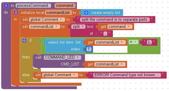
The new bits:
First the command is split into a list using the comma as the seperator. Each list element is a single character.
![]()
then the first list element is compared to an “L”

if it is an “L” the COMMAND_LED procedure is called.
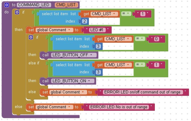
COMMAND_LED is a new procedure and deals only with LED commands. First it checks the LED number (the second list element)

and then sets the LED control button depending on the value of the third list element.
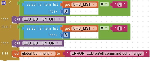
I have also started to add error trapping. By using 2 if statements and an else statement we are trapping non correct values. If we used if = “0” turn LED on else turn L:ED off. Any non 0 value would be turn on the LED.
At the moment I just have comments but these can be replaced with something like a pop-up error message.
Download Arduino Sketch. Example Project Part 4: Complex control codes II
Download ARD_HM10_AI2_Single_LED_07.aia
All this work and we are still only turning a single LED on or off. Hopefully though, you should be able to see how the Arduino sketch and the app can now be easily extended and adding new commands should not be straight forwards We see if this is true in the next part.
Example Project Part 5: 3 LEDs and 3 switches
Here we add more LEDs and more switches and expand the control codes to accommodate them.
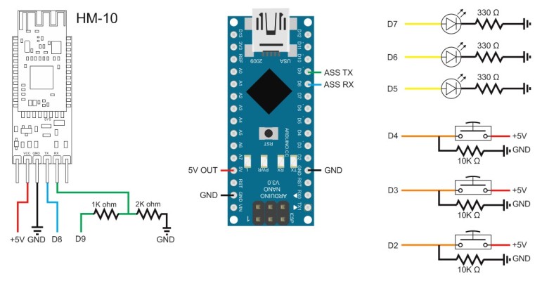
Circuit
Add switches to pins D3 and D4. Add LEDS to D6 and D7.
I’ve moved things around a bit to make the switches easier to access but the circuit is basically the same.
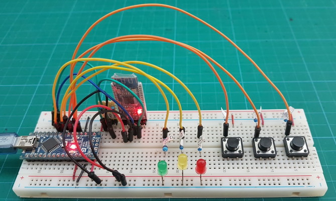
Arduino Sketch. Example Project Part 5: 3 leds and 3 switches
I do not go in to how the sketch was created. It is the same as the one used in the Bluetooth Classic guide (I copied the Bluetooth Classic sketch) so if you want to know more see the Turning a LED on and off with an Arduino, Bluetooth and Android. Part III 3 LEDs and 3 Switches post. This goes through my usual process of how I create then refine sketches.
A couple of notes though. The command sent to the app is created as required. A temp command variable is used and the values are replaced before transmitting the command.
For the received commands I am assuming the received values will be correct and in range and so use the value directly from the command. The LED pins are stored in an array, this means I can use the LED number from the command as the index to the LED pin array. I no longer need to check which pin it is.
/* * Arduino, HM-10, App Inventor 2 * * Example Project Part 5: 3 leds and 3 switches * By Martyn Currey. www.martyncurrey.com * * Turn LEDs on and off from an Android app via a HM-10 or from a physical switches connected to the Arduino * Uses the following pins * * D9 - AltsoftSerial RX * D8 - AltsoftSerial TX * D7 - LED + resistor * D6 - LED + resistor * D5 - LED + resistor * D4 - Button switch * D3 - Button switch * D2 - Button switch */ // AltSoftSerial uses D9 for RX and D8 for TX. While using AltSoftSerial D10 cannot be used for PWM. // Remember to use a voltage divider on the Arduino TX pin / Bluetooth RX pin // Download from https://www.pjrc.com/teensy/td_libs_AltSoftSerial.html #include <AltSoftSerial.h> AltSoftSerial BTserial; // Variables used for incoming data const byte maxDataLength = 20; char receivedChars[21] ; boolean newData = false; // Constants for hardware const byte SWITCH_PIN[] = {2,3,4}; const byte LED_PIN[] = {5,6,7}; // general variables boolean LED_State[] = {false,false,false}; boolean switch_State[] = {false,false,false}; boolean oldswitch_State[] = {false,false,false}; void setup() { for (byte pin = 0; pin < 3; pin++) { // Set the button switch pins for input pinMode(SWITCH_PIN[pin], INPUT); // Set the LED pins for output and make them LOW pinMode(LED_PIN[pin], OUTPUT); digitalWrite(LED_PIN[pin],LOW); } // open serial communication for debugging Serial.begin(9600); Serial.print("Sketch: "); Serial.println(__FILE__); Serial.print("Uploaded: "); Serial.println(__DATE__); Serial.println(" "); // open software serial connection to the Bluetooth module. BTserial.begin(9600); Serial.println("AltSoftSerial started at 9600"); newData = false; } // void setup() void loop() { for (byte switchNum = 1; switchNum < 4; switchNum++) { checkSwitch(switchNum); } recvWithStartEndMarkers(); // check to see if we have received any new commands if (newData) { processCommand(); } // if we have a new command do something about it } /* **************************************** * Function checkSwitch() * checks the status of a button switch and turns an LED on or off depending on the switch status * * passed: * * global: * switch_State[] * LED_State[] * oldswitch_State[] * * Returns: * * Sets: * switch_State[] * LED_State[] * oldswitch_State[] */ void checkSwitch( byte pos) { // pos = 1,2,3. Array pos = 0,1,2 so convert by subtracting 1 pos = pos-1; // very simple debouce. boolean state1 = digitalRead(SWITCH_PIN[pos]); delay(1); boolean state2 = digitalRead(SWITCH_PIN[pos]); delay(1); boolean state3 = digitalRead(SWITCH_PIN[pos]); delay(1); if ((state1 == state2) && (state1==state3)) { switch_State[pos] = state1; if ( (switch_State[pos] == HIGH) && (oldswitch_State[pos] == LOW) ) { LED_State[pos] = ! LED_State[pos]; // flip the status. // Rather than have a long list of possible commands I create the command as required. // Values in the temp command are replaced depending on which button switch has been pressed. char TMPcmd[8] = "[L,1,0]"; TMPcmd[3] = pos+1+48; // pos+1 should be 1,2, or 3. convert a numeric value to ascii by adding 48. TMPcmd[5] = LED_State[pos]+48; // LED_State should be 0 or 1 BTserial.print(TMPcmd); digitalWrite(LED_PIN[pos],LED_State[pos]); Serial.println(TMPcmd); } oldswitch_State[pos] = switch_State[pos]; } } /* **************************************** * Function processCommand * parses data commands contained in receivedChars[] * receivedChars[] has not been checked for errors * * passed: * * global: * receivedChars[] * newData * * Returns: * * Sets: * receivedChars[] * newData */ void processCommand() { Serial.print("receivedChars = "); Serial.println(receivedChars); if (receivedChars[0] == 'L') // do we have a LED command? { // we know the LED command has a fixed length "L10" // and the value at pos 1 is the LED and the value at pos 2 is 0 or 1 (on/off). // 0 and 1 is the same as LOW and HIGH so we can use 0/1 instead of LOW/HIGH byte LEDnum = receivedChars[1] - 48; // convert ascii to value by subtracting 48 boolean LEDstatus = receivedChars[2] - 48; digitalWrite(LED_PIN[LEDnum-1],LEDstatus); LED_State[LEDnum-1] = LEDstatus; } receivedChars[0] = '\0'; newData = false; } // function recvWithStartEndMarkers by Robin2 of the Arduino forums // See http://forum.arduino.cc/index.php?topic=288234.0 /* **************************************** * Function recvWithStartEndMarkers * reads serial data and returns the content between a start marker and an end marker. * * passed: * * global: * receivedChars[] * newData * * Returns: * * Sets: * newData * receivedChars * */ void recvWithStartEndMarkers() { static boolean recvInProgress = false; static byte ndx = 0; char startMarker = '['; char endMarker = ']'; char rc; if (BTserial.available() > 0) { rc = BTserial.read(); if (recvInProgress == true) { if (rc != endMarker) { receivedChars[ndx] = rc; ndx++; if (ndx > maxDataLength) { ndx = maxDataLength; } } else { receivedChars[ndx] = '\0'; // terminate the string recvInProgress = false; ndx = 0; newData = true; } } else if (rc == startMarker) { recvInProgress = true; } } } |
Updating the app
Save the current project as ARD_HM10_AI2_3LEDs_3Switches_08
A lot of the hard work has already been done. In this part we simply duplicate controls and extend the if/then condition list in the COMMAND_LED procedure.
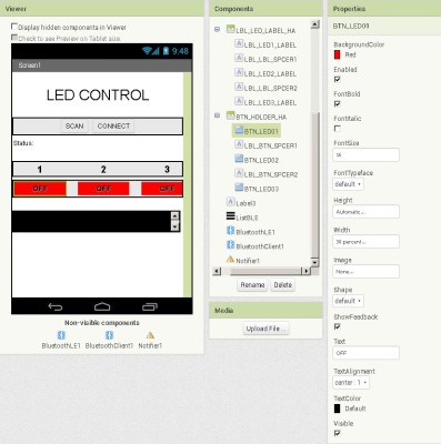
First we add 2 more LED control buttons. I have also added spacer labels between the buttons.
The spacer labels are:
Height – Fill parent
Width – 5 pixels
HasMargins – unchecked
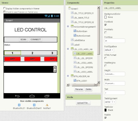
Above the buttons I have added labels to identify the buttons. The label sizes are 30% width the same as the buttons. I have unchecked the HasMargins property so that the sizes match correctly. The labels also have spacer labels separating them the same as the buttons..
Of course, now that we have new buttons we new blocks to look after them.
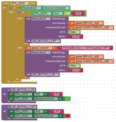
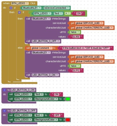
I simply duplicated the BTN_LED01.Click procedure and changed the references to BTN_LED02 and BTN_LED03 and updated the command to be sent. You can do the same with the LED_BUTTON_ON and LED_BUTTON_OFF procedures. Copy them and then change the references.
This takes care of the button clicks now we take care of the extra commands the app may receive.
Since we are still only receiving LED commands we do not need to change the processCommand procedure and only need to update the COMMAND_LED procedure.
We now have commands for LED #2 and LED #3. All I have done is copy the original blocks and updated the values being checked and which button on/off procedure that is called.
The COMMAND_LED procedure could be made a little smaller. For example, we know, regardless of which LED is being used, the on/off code should be 0 or 1. We can check for this at the beginning rather than 3 separate times. Another option is to put the button elements in to a list and then use the LED number as the index to the list. Similar to how the Arduino sketch now works. I’ve kept it simple and simply have 3 similar blocks of code.
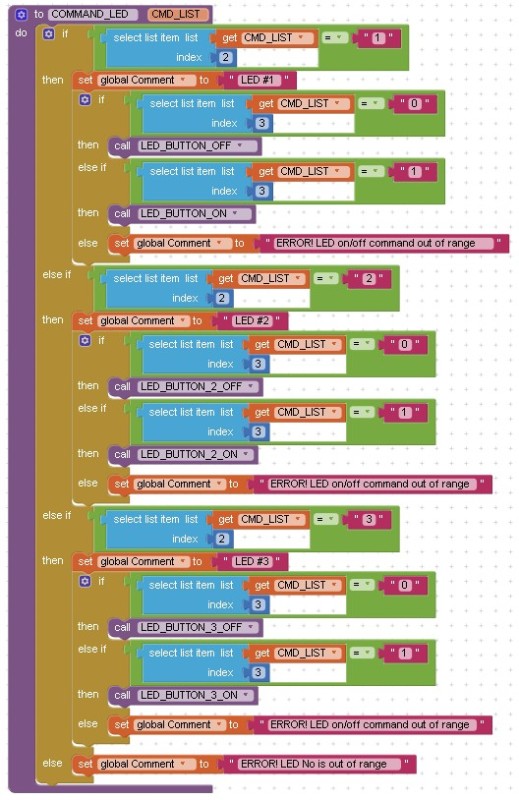
If you read the previous parts you should remember that the LED command has been split in to a list and element 1 is the “L” for LED, element 2 is the LED number (1 to 3) and element 3 is the on/off code (0 or 1).
Element 1 is checked in the processCommand procedure and if found the command list is passed to the COMMAND_LED procedure.

In the COMMAND_LED procedure element 2, the the LED number, is checked

and if a 1, 2 or 3 element 3, the on/off code, is then checked. If the app finds a “0” or a “1” the button off or button on procedure is called.
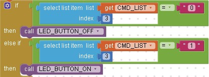
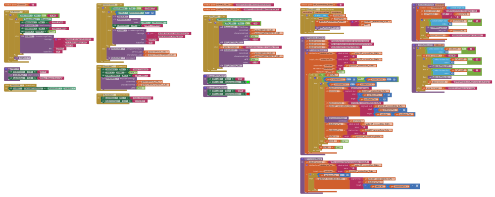
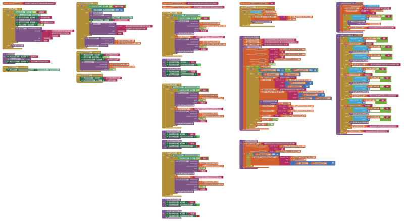
And that’s it. We are able to control 3 LEDs. Here are the blocks
Download Arduino Sketch. Example Project Part 5: 3 LEDs and 3 switches
Download ARD_HM10_AI2_3LEDs_3Switches_08.aia
In part 2 we add a slider to control one of the LEDs. See Arduino, HM-10 and App Inventor 2: Adding a slider



Your introduction to HM-10 is super useful. These kinds of resources will really help. The 3 LEDs look like a work of art.
E
Excellent tutorial.
For those of us that would like to simply wire up the components…and test…
Might I recommend to compile the app,…and have it available for download on google apps?
We can always come back and tweak the code to our liking afterwards….
Great job BTW…
Thanks a lot!
Grazie, grazie, grazie!
Super tutorial!
Hello~
Very good~
but can you make the effect like this video? Thanks~
https://www.youtube.com/watch?v=yUivJNQ_hXM
I will try to add a slider in the near future. For now see https://www.martyncurrey.com/arduinobtcontrol/
This is for Bluetooth Classic but the technique is the same.
Hi~
Good~
OK!
Just added a new guide just for a slider.
See https://www.martyncurrey.com/arduino-hm-10-and-app-inventor-2-adding-a-slider/
First of all thank you for such great tutorial and your time. I am just wondering, is it the same approach for HM-08?
I’m sorry HC-08.
Similar but not exactly the same. Start with the data sheet http://www.wavesen.com/mysys/db_picture/news3/2015121885146101.pdf
Google has lots of hits.
Hello~
sliding bar
You can refer to
https://apk.tools/details-control-for-arduino-bluetooth-4-0-hm-10-apk/
It is a pity that the HM-10 has limited capabilities. For example, output data to RAW DATA. To obtain information unilaterally without the need to establish a connection. For example, we have 10 contact sensors on the HM-10 (without an additional chip). And we need to watch them constantly. When the sensor is triggered, output information to the device (for example, the LED lights up).
This is a phenomenal walkthrough of creating an app with App Inventor, BLE and Arduino. Thank you so much for sharing this knowledge in such a clear and concise way. I have learned so much. Really looking forward to further additions to this topic. Again, thank you!
Hi! thanks for this amazing tutorial, I have been waiting one year for it!. I have one question: did you use software serial for any particular reason? Can I use the hardware serial pins of the Arduino and make it work the same? The problem of software serial is that it does not work for high baud rates such as 115200, when new sensors work at this high rates.
Yes, you can swap the software serial to hardware serial.
I use software serial or altsoftserial so that I can use the hardware serial + serial monitor. It also makes uploading new code easier. When using hardware serial you need to remove the connections when uploading new code.
For my own projects that need fast communicatiopn, after everything is working, I change the software serial to hardware serial.
THANK YOU KIND SIR
I had to use this for a science fair
AND YOU DID EXACTLY WHAT I NEEDED
I MEAN I CAN’T THANK YOU ENOUGH
me 2
What labeler do you use for the labeling of your resistors and such? The small print and tape is difficult to find. Thank you.
They are A4 sized adhesive sheets. I print them and then cut them.
Nice Post Thanks for sharing keep it up.
Excelente, sem muita voltas, parabéns. Deus abençoe você. Partilha é sempre aprendizado.
Sorry, i answered in portuguese. God Bless U a lot. Share our knowledge is a big learning to yourself.
Congratulation….
Yes, A lot of this is to help me learn.
Happy that is is helpful.
Amazing guide and very well laid out and organized! Thank you for making it available. Still working through the codes to change my Bluetooth Classic to BLE, but you have laid out an excellent road map!
thanks for the kind words and am glad it is useful.
I really impressed at your post. Thanks for sharing.and i just have a question. by any chance, Could App inventor2 scan Hm-10 as beacon mode? not ble mode.
Use the BLE.ScanAdvertisements block.
You can see all the available blocks at http://iot.appinventor.mit.edu/#/bluetoothle/bluetoothleintro
Arikel yg sangat bagus.. bagaimana cara aplikasi auto connek ke device terahir .. trimakasih
Terimakasih artikel yg sangat bagus.. bisakah bantu sy aplikasi autoconnek ke device terahir trims..
gracias desde republica dominicana, eres el mejor.
Thank you very much for this very detailed and informative post.
Greetings from Slovenia
Thank you very much for this great website. It helped me so much.
I tried to write a programm with app inventor that sholud connect to ble devices. On my Samsung Galaxy S7 this works fine. On a cheap alcatel smartphone the app doesn’t find any device also I can find the ble device in the android bluetooth settings. Any idea what I do wrong?
On the alcatel confirm what version of BLE it has.
Use one of the BLE scanner apps to connect to the HM-10. If this works then AI2 should work.
If the BLE scanner app finds and can connect to the HM-10 then the issue is likely with AI2 and all I can suggest is ask on the AI2 forums.
I tried with Serial Bluetooth Terminal App now. I can find and connect the device with this app as ble device. So the problem seams to be mit appinventor, right?
I wrote the problem in the mit app inventor google group but I didn’t get any usefull answer till now. So if anyone has an idea what the problem could be please let me know.
Now I found out, that the app works, when I activate google location. Why ever…
I’m searching how to let MIT APP receive data from HM-10 for a while. This the greatest guide I found in the internet. Thank you so much!
At the beginning it always fails. I tried to change data types, use explicit receive function instead of “registerXXX”, etc, but not work at all. Finally I found it’s the version issue. Currently the latest BLE extension is version of 2. But the author used is 20170818. (no typo. the version number styles are hugely different, don’t know why… ) Maybe the latest version has a bug on this. At least I have not found a way to make it work.
Besides, the two versions have another difference. In terms of writing a sting through APP to BLE, the old one will append “NULL” to the end of the string. But new one will not.
Can u help me with the same
I have a problem, it does not work for me. The issue is that it finds the bluetooth and connects (the bluetooth LED remains fixed). But in the Arduino sketch it never enters the condition: if (ASSserial.available ()), I’ve checked it by setting an else.
Any suggestion of why does not enter the serial is activated?
Is it possible to maintain the connection between different windows?
No. Each screen requires its own connection. You can get around this by using pseudo screens. See https://www.martyncurrey.com/app-inventor-2-pseudo-screens/
Excellent, very good tutorial! I wish the tutorials on the Internet were like that. It helped me a lot, very clear and friendly. Martyn, thank you very much. Greetings, Pedro from Chile.
Thank you for your kind words. Glad the article was helpful.
Best thing since sliced bread.
u da man! (or woman )
note this also works with the clone ZS-040
Hello, thanks for a good tutorial. I have only one problem with the application. I need to check status of LED (on/off) when the application starts and show it in application. Is there any easy solution? Could you give me an advice?
there is but to make a robust system is not so straight forward. For example you cannot set the buttons in the app until the app is connected and the app will not be connected when the Arduino first starts.
Probably the easiest way is to add a connected command:
When the app connects send a connected command to the Arduino.
When the Arduino gets the connected command read the LED pins and send back appropriate status commands.
When the app gets the status commands set the app buttons accordingly. If you are using the LED commands from the example above you can use the LED commands.
Hi
I want to send many characters for example ( channel 1 is send “A” for on led and for off send “a” . channel 2 is send “B” for on led an for off send “b”
But I don’t know how to send an ACIi command !
Please help me !!?????
And I don’t want use of uuid for this app
Because I want this app connect with all Bluetooth modules HM-10
Hi Martyn Currey,
Thank u very much for u r tutorial. I understood more about BLE and App Inventor.
I am working on BLE HM10 distance measurement in mobile app. Could u help me to how to measure the BLE distance in mobile and if the distance is exceeded, send the command to BLE?.
Dear Martyn, your blog has many details and easy to read. Thanks to you and I was able to build the block with the almost same code structures as you did. I revised the light button image change when button clicked. Image back to original when user click again.
The code as below image.
https://imgur.com/a/RFjZdR1
I tested the bluetooth module with the debug app provided by manufacturer – Jinanhuamao. It worked.
It won’t work as long as I control it with my app inventor app. The LED only blink for one second and it goes off immediately when I clicked the button.
Anything wrong?
I would be appreciated if you could help.
Thanks so much for this helpful blog and helped me a lot.
Best regards,
Kevin
By click do you mean regular button click?
In the blocks you are using touchdown and touchup. This means as soon as you release the button the LED turns off.
Yes, I used Click for turning LED light on and off.
For motors I used touch up and down.
But seems they both has same problem, click then LED flash then off immediately, touch down the motor move then not move imdediately.
Thanks for your reply.
Double check what the app is actually sending.
Double check what the sketch is actually receiving and use the serial monitor to help debug.
Print the values you are receiving from the HM-10.
Print status notes such as “LED ON”, “LED OFF”, MOTOR ON:, etc.
hey mirtyn. i have a question and need your help . when we received strings from arduino in android. how can we detect for example it is temperature and print it in label?
i mean both humidity and temperature received but how to separate them each other and print in two label separately.
See the final part of the guide above where I introduce more complex commands.
In the example above I use Lxx to indicate LED, simply change this to Txxxx to indicate temperature. Or, if sending data to AI2 using comma separate values, such as T,27. This makes it a little easier to handle in the blocks.
Hi Martyn! A few days ago i tested the app with the hm10 module and it worked well. But now when I press the scan button text changes but the list of devices does not come up. The app was tested on different phones and the results were the same. What could go wrong, any ideas?
Hi Martyn,
Great tutorial. Thanks!
Parts 1 & 2 worked for me no problem. But Part 3 does not work right for me. The LED only flashes on quickly, then immediately off, when I try to turn it on via the app.
One a side note, the link to the file “ARD_HM10_AI2_Single_LED_06.aia” downloads a file called ARD_HM10_AI2_Single_LED_CORRECTED.aia
The link for the file “ARD_HM10_AI2_Single_LED_07.aia” also downloads a file called ARD_HM10_AI2_Single_LED_CORRECTED.aia
The good news is that those two files, despite having the exact same name, are different in content.
Re Part 3….Never mind! I’m an idiot.
But the file name issues still might need to be fixed.
I’m trying using arduino beetle but i can’t find my devices and also others using the app
I just want to thank you for taking your time writing this.
Very clearly explained and super detailed.
Thanks!
i download 3led .aia not work scan not see HM-10
from Play-store download work
what is problem
I made an APP using BLE but I’m unable to get the extension of BLE in second….plz help me
Hi Martyn currey!, can u help me to receive string? Mean i would set label as receiving string i try do it as: https://imgur.com/weeJfHq what source code i should use arudino?
Pls dont send me there http://iot.appinventor.mit.edu/#/bluetoothle/bluetoothleintro ;)
sorry for my english ;)
See the last couple of examples above.
Thanks for the tutorial. I have a problem. Some times the connection is successful, but most of the time I am getting the error “Connection status was set to OS code 133”. Please help me.
Excellent tutorial, thank you :)
hi.. great tutorial,..thank you
I have built a device to detect level of liquid .. I have added bluetooth functionality to it and had even built an app ,,but unfortunately the person who built is not available any more.. I need to rebuilt the app.. I was researching this Inventor iot and realized it can be done fairly easily(off course effort is needed). right now i am using Uart to demonstrate the state on a mobile,. its very similar to the LED on/off.. the microprocessor on our device send out two states 1& 0.. (which represent two levels high & low).. can you help me built the app for android,.. how is the costing
rgds suresh.c
Unfortunately I do not have time to offer this kind of service. If you ask on the app inventor forum/user group I am sure somebody there can help you.
https://groups.google.com/forum/#!forum/mitappinventortest
Hi, Im having problems with the base connect example. When I run the app it wont find my module, the list doesnt even come up. When I use the BLE terminal app it can both see and connect to the module and even send and receive data. Im prety sure its a clone and not an origional HM 10. If anyone knows how I can connect it with AI2 app hlep would be apritiated.
HI Sir,
Just want express gratitude for such amazing technical sharing. Thanks! : )
You can eliminate the Arduino and run code directly on the App and HM-10.
https://www.youtube.com/watch?v=PINCucGRhA8
I have a full HM-10 guide at https://www.martyncurrey.com/hm-10-bluetooth-4ble-modules/. This includes using the HM-10 without a microcontroller.
thanks for this document. I think ble string received problem. I am sending arduino ASSserial.print(“a” ); to android apk. But string received not working. I added clock and blue block read string , after then working string received. But wrong. string received with clock block but string only own sent led status info to arduino. I changed arduino program, 1 and 0 with a and b. unfortunately still received 1 and 0.
could you please check this.
regards
For BLE don’t use a clock, use the and the registerForStrings block and the .stringsReceived block. After registering the stringsrecieved block should be called when ever a string is received. If this is not working double check the UUIDs for the service and the char.
Thanks but I tried your program. Program don’t call string received block. I changed clock block idea but was wrong, I know. I tried arduino program other ble terminal program. arduino send info to android terminal program. Arduino program OK.
I can’t any answer from arduino. your program using global variable for uuid’s. therefore, correct uuid I am sure. Ble library is last version from appinventor.
everything good working but still, string received not working.
Regards
I read your other page, ble scanner app I used. if I pressed only custom char R, Arduino sent char to app but I can’t see any change on the screen. But I pressed N (green) I saw chnage info come from arduino.
How can I enter Notify mode in app inventor. Register block have service uuid and char uuid. I can’t notify mode. May be set with AT command . now my mmodule role =0 my module is at-09 and name is BT05
greatfulll ..
your explain about the MIT and arduino powerfulllllllll…
Brilliant tutorial!
Thank you for taking the time to write it. This has helped me immensely in using BLE with App Inventor.
Thanks again!
Can anyone help with the BLE chat app…
Sending string and receiving string pls…
I don’t have the link but one of the AI2 examples is a BLE chat app. Google can help.
Hi Martyn,
totally great and very helpful your tutorials, I have learned a lot with that.
I want to receive a string with AI2 over BLE which is send by an electronic with this protocol: Some Text here. From the c sourcecode of the mirco it is sending this way:
com_putchar(0x02);
com_putchar(“Some Text here”);
com_putchar(0x03);
I tried a lot of ways to get this information into a label in AI2 but no one works as expected. I always get different incomings, only sometimes the correct string. If I check with an terminal directly connected to the micro it is sending everything correctly, everytime.
Can you give me an idea how to check for STX and ETX, as it is not possible to check as a string right? I have at this moment no idea how to replace the marker in the process_buffer as these are non printable chars.
Thanks
UWE
Unfortunately this is not so straight forward in AI2. You can change the start and end markers to com_putchar(0x02); and com_putchar(0x03); but you will need to change the blocks that check the start and end markers (https://www.martyncurrey.com/wp-content/uploads/2017/10/ARD_HM-10_AI2_03_06.jpg)
Using ascii values rather than strings is not built in but there are functions that can help. Start with search for “Ascii CHR ASC procedures” (http://ai2.appinventor.mit.edu/?galleryId=6407304567324672#) and also search for “ai2 get the ascii value of a string”
Hello
I’m having problems runing the app using a smartphone with Arduino’s latest version (8.1.0). The list doesn’t come up.
But when I try the app in an older phone, it works properly.
Any idea of what could be wrong?
Thanks in advance
Try updating the BLE extension.
Download the latest version from https://www.dropbox.com/s/2aagtvvxe76jjfs/BLE-with-new-ConnectDevice.aix?dl=0 and replace the existing extension. No need to delete the old version upload the new version over the older version.
Just tried the updated extension on Android 9 (Samsung S10) and the list came up.
Dear Martyn
It works properly.
Thank you very much.
Hello i tried your example .aia and they dont work at my system.
When i start scanning no list appears. :S (=no devices found)
But when i try the compiled code from google store everything is alright?
Do i have a problem with App Inventor?
No problem you just need to download the latest BLE extension from https://www.dropbox.com/s/2aagtvvxe76jjfs/BLE-with-new-ConnectDevice.aix?dl=0 and replace the existing extension. No need to delete the old version upload the new version over the older version.
I also have the same problem.
I tried to update the extension through your link, but still no list appears during scanning.
I have a HM-11 clone and I have already flashed the firmware. I can connect to the module through several BLE scanner apps and your App in the Google Store.
But I need to get this working, so that I can build my own apps in the App Inventor.
Any ideas?
Thank you
how do you get the bluetoothLE1 on the app inventor ?
You need to add the BLE extension, see the article above.
The best article on the topic I found on the internet. People like you are the real game-changer for beginners. But one more question, How do I pass UUID’s if I have a custom made BLE profile which is128 bits long(not 16-bit hex code as in your case for BLE SIG defined profiles).
Assuming the BLE device follows the standard then the custom attribute type will use the base UUID 0000xxxx-0000-1000-8000-00805F9B34FB and your value replaces the xxxx. The HM-10 above uses the same method.
UUID 0000xxxx-0000-1000-8000-00805F9B34FB is a special UUID that uses Bluetooth SIG-Adopted Attributes. See https://www.bluetooth.com/specifications/gatt/characteristics/ for a list.
Hi, I use your tuto to make an app for control an arduino with BT and HM-10 clone module. I try to send string with WriteStrings but when I click on button to send string, I get an Runtime error : For input string “0000ffe1”. the string was send is [GD]. Android version 8.1 and lastest extension
Can you help me ? Thanks a lot a very good tuto
Did you update the BLE extension?
Hi Martyn, I have followed your two way led control program and was unable to fetch data to my app from the hm 10 but the sending part does work perfectly and one more thing when I use the same Arduino code and a BLE terminal app I can see the data coming from the hm 10, so probably the problem is it the MIT app. Do you have any suggetons.
I have used Arduino Uno and Hm10(clone)
I’ve just tried a couple of the above examples with the latest AI2 and BLE extension and they both worked fine.
ARD_HM10_AI2_Single_LED_05.aia
Example Project Part 2: Turn an LED on and off 2way control
Example Project Part 5: 3 LEDs and 3 switches
ARD_HM10_AI2_3LEDs_3Switches_08.aia
Without knowing more about your set up all I can suggest it for you to double check all connections and the output in the serial monitor.
Thank you so much Mr. Martyn. I have spend a lot of time trying to grasp the HM-10 and the App Inventor alltogether, and you just save me tens of hours with your excellent tutorial. God bless you Mr Martyn!
Pablo
I was having the same problem but figured out a solution, make sure that your location services are on. After android 6.0 BLE scanning requires your location to be on. Hopefully, this works for you
I want to get the sensor’s sensing output to be displayed in the app inventor side via Bluetooth low energy module HM10. But I faced some problem to do this.
I design a terminal where four buttons are used for the initialization purpose of the Bluetooth module. I declare a status label for the result of the successful connection of the Bluetooth module and found ok to connect with the Bluetooth module. After a successful connection when I send ‘0’ to the Bluetooth which is connected via a microcontroller and receive ‘0’ in the app display and when I send ‘1’ then display ‘1’ in the receive lebel of the app. But in the microcontroller programming, I used ‘if-else’ condition: when send=0, then display 0 and when send = 1, then display sensor value. So when I send ‘1’ then in the app the sensor value to be display but this is not coming but I checked in the oscilloscope, and see that the sensor value is coming.
Therefore I request you to give a suggestion for this problem.
Hi Martyn,
thanks for nice explanations and working code.
I have two way communication between AVR and Android and it works like a charm. I need however after sending some data to Android, set BLE module to Sleep mode (AT+SLEEP2 command). This does work only if I do not use BLE1 Register for strings block. But of course if I don’t use Register for strings block then two way comm does not work. Is there any work around to have two way communication and still put BLE module to sleep mode?
A HM-10 can only accept AT commands via UART when there is no wireless connection so you need to reset the module in some way to re-enter AT command mode.
A HM-10 can accept AT commands wirelessly when it has a wireless connection, this means you would need to send the command from the Android side rather than the MCU. Check the data sheet for full details.
IS IT POSSIBLE TO TOGGLE THE HM10 PINS VIA ANDROID MIT APP INVENTOR?, I CANT GET IT TO WORK, IF I SEND AT COMMAND USING WRITE STRINGS OR WRITE BYTES OR REGISTER FOR STRINGS OR NOT REGISTER STRINGS ,HM 10 WONT RECOGNIZE IT IN ANY OF THAT, WHAT ITS DOES IS JUST OUTPUT THE COMMAND ON ITS TX PIN , AND IT ALSO DOES NOT RESPONSE “OK…”, IM TRYING TO CONTROL A MOTOR WITHOUT AN ARDUINO ,ONLY HM 10, IS IT POSSIBLE???
Have a look at the HM-10 guide https://www.martyncurrey.com/hm-10-bluetooth-4ble-modules/
HM 10 IS V708 AND I ALREADY SET IT TO MODE2 SLAVE/PERIPHERAL MODE, DOES THIS ONLY WORK IF HM-10 TO HM-10 CONNECTION AND NOT HM-10 TO ANDROID??
Unfortunately I don’t know. It’s been a while since I used the HM-10 and I had no need to send AT commands from Android.
You can try contacting HMSoft.I have found their customer service to be fairly good.
support@jnhuamao.cn
If you don’t get a reply, send a reminder.
THANKS FOR REPLYING, I FOUND THE CULPRIT , BECAUSE OF THE NULL TERMINATOR WHEN SENDING A STRING .ON MIT APP INVENTOR JUST SET.BLE.NULLTERMINATESTRINGS== FALSE. HM10 DOESNT LIKE THE NULL ,
NOW IT WORKS FLAWLESSLY USING ANDROID TO SEND AT COMMANDS.
Hi,
If i update the AIX bluetooth lib, will your examples work on Android and wich version ?
Excelent BLOG!!!!
Hi Martyn
Many thanks for your, Oh so, helpful tutorial. Much appreciated.
I am trying to upgrade an app from Classic to BLE. I am using an HM-18 (which claims to be compatible with the HM-10). All goes well, the app scans and connects as per your instructions and I can send simple strings from my Android phone and rean them on your simple monitor program (serial_in_serial_out). But after about 10-15 seconds the serial monitor shows OK+LOST and no more communication takes place.
Is this correct? IS it possible to keep the connection alive longer or revive it easily?
Many thanks for your help.
Regards
Please be aware I haven’t used the HM-18 and I haven’t used the HM-10 for a while now.
The connection should not be broken like this. I have a couple of projects that use the HM-10 and once they are connected the connection is very reliable.
Check the data sheet for the HM-18 and find out how to break a connection (there may be more than one method) and then see if you are inadvertently doing this (for example long strings).
You can also try one of the BLE scanner/enquiry apps. Make a connection with the app and see if the connection is broken in the same way.
Just wow, it’s very organized! Thank you for making and sharing it.
very good organized tutorial for beginners, step by step guide to build the app and understand all the almost all the functionality of AI2.
I recently purchased a HM10 module for Arduino UNO and was looking for some resources/help to begin with and my search ended on this page.
Thankyou very much
Hello, this really is a very good description, respectful.
For weeks I have had the problem that the entire string can no longer be transmitted from a limited BLE range.
I then get the message “Bad Arguments to + …” The app continues to run in the background and is also stable. Is it possible to simply hide this message?
I have tried a lot so far, but all without success.
Best Regards Danny
You can trap the error using the Screen.ErrorOccurred block. (you will need to find the error code to use). A better solution would be to find out why you are getting the error. I would start with making sure you are using the latest BLE extension.
Hello Martyn,
I got with this command
Screen.ErrorOccurred has been accepted for a time.
However, this error “Bad arguments for +” and “Select list item: List index too large” blocks sporadically again and again.
These errors are not error numbers but messages, right? Kind regards, Danny
List index too large means you are trying to use a list element that does not exist.
For example, if you have a list with 10 items in it and try to read item 11 you will get this error.
your are such a genius it’ really help me
I’m trying to make code for auto connect with hm10 module can you guide me
Hi Martyn
Many thanks for your, Oh so, helpful tutorial. Much appreciated.
I created an app with App inventor as shown in
“Example Project Part 2: Two-way control of an LED”,
but it doesn’t work .
Also the download link to
ARD_HM10_AI2_Single_LED_05.aia
does not work .
Can you help me ?
Thank you very much
Thank you so much Martyn.
Some download links are broken :(
I will be happy if you help :)
ARD_HM10_AI2_Single_LED_05.aia
I kept forgetting to fix the link. Thanks for the reminder.
Should be working now.
There is still an error when trying to download your
“ARD_HM10_AI2_Single_LED_01.aia”
ARD_HM10_AI2_Single_LED_02.aia”
ARD_HM10_AI2_Single_LED_03.aia
“ARD_HM10_AI2_Single_LED_04.aia:
“ARD_HM10_AI2_Single_LED_06.aia”
files from the link provided :< So sorry to trouble you but is it okay if you look into it again?
There is an error when trying to download your
“ARD_HM10_AI2_Single_LED_01.aia”
ARD_HM10_AI2_Single_LED_02.aia”
ARD_HM10_AI2_Single_LED_03.aia
“ARD_HM10_AI2_Single_LED_04.aia:
“ARD_HM10_AI2_Single_LED_06.aia”
files from the link provided:( Please help
fixed. Again….
HI :( When I try to upload and run the apps for
“ARD_HM10_AI2_Single_LED_01.aia” and “IoT_BaseConnect.aia”, nothing happens when I click the scan button. I have ensured that my location is on. I know that a list of available BLE devices is supposed to appear but the black coloured list doesn’t seem to appear at all. I’ve tried this with other devices and the same problem persists. do you have any suggestions on what I may do?
Did you update the BLE plugin?
Hi Matyn, thanks for amazing work you did! Hope you’ll be able to help me with this: I would like to use Hm-10 as battery percentage reader. Is there a way to configure it to use BLE GAT Battery service?