Connecting 2 Arduinos using 2 HM-10s is fairly easy. It is straight forward to make a connection and once the connection is established the HM-10s UART layer does all the work for you. The UART layer does mean you have no control over the actual BLE details though.
To make a connection, all you need to do is set the main module to manual connection, set to Central mode, and then use the connection command AT+CON.
Once connected the HM-10 transfers data by setting the value of a custom characteristic to the data you are sending. The receiving device then reads the value.
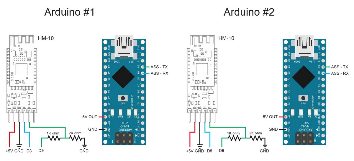
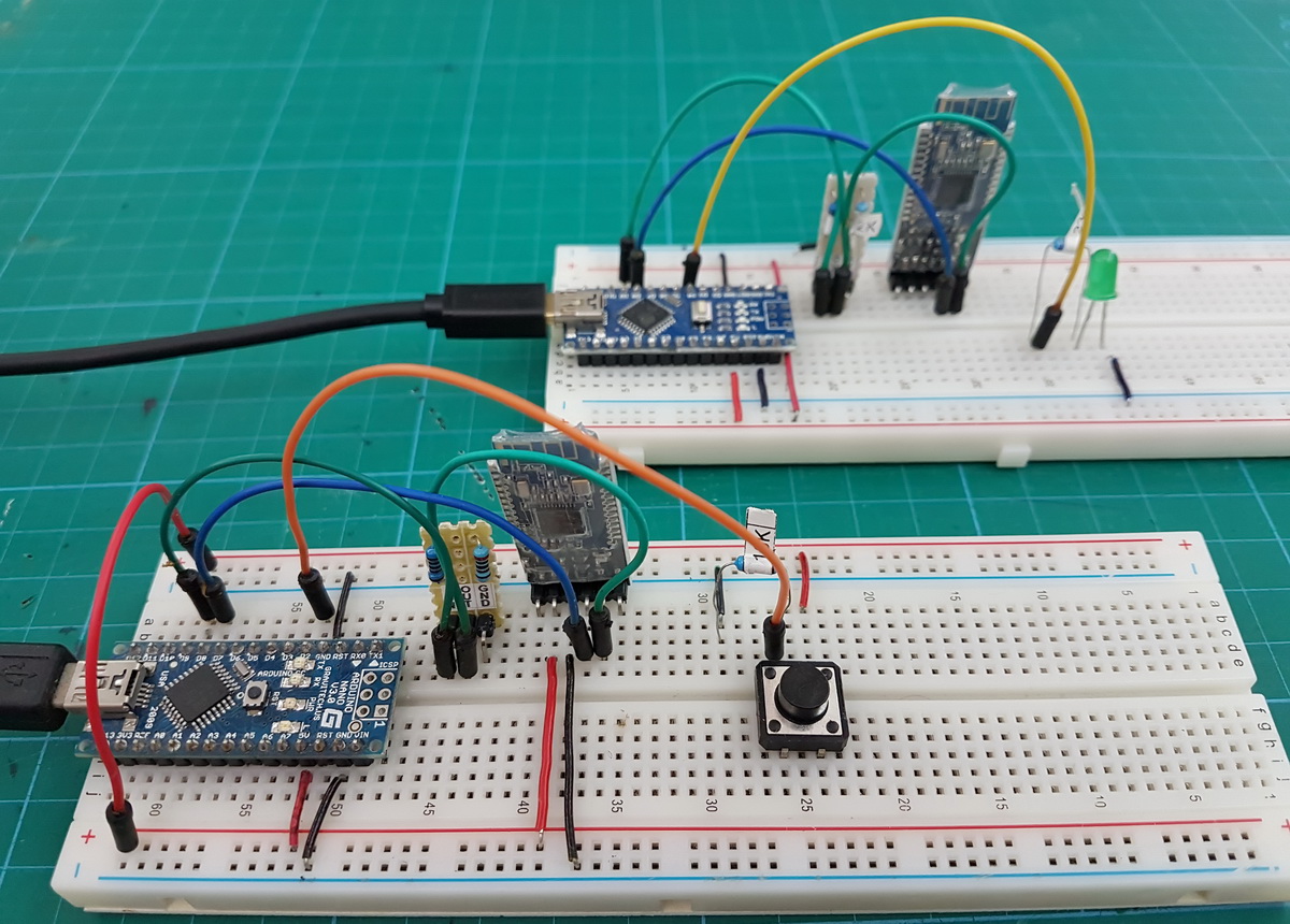
For this example I have 2 Arduinos and each Arduino is connected to a HM-10. Both are wired up exactly the same.
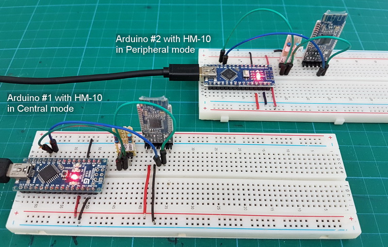
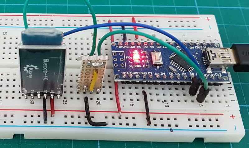
If you are wondering where the second HM-10 is getting power from; the connections are round the back.
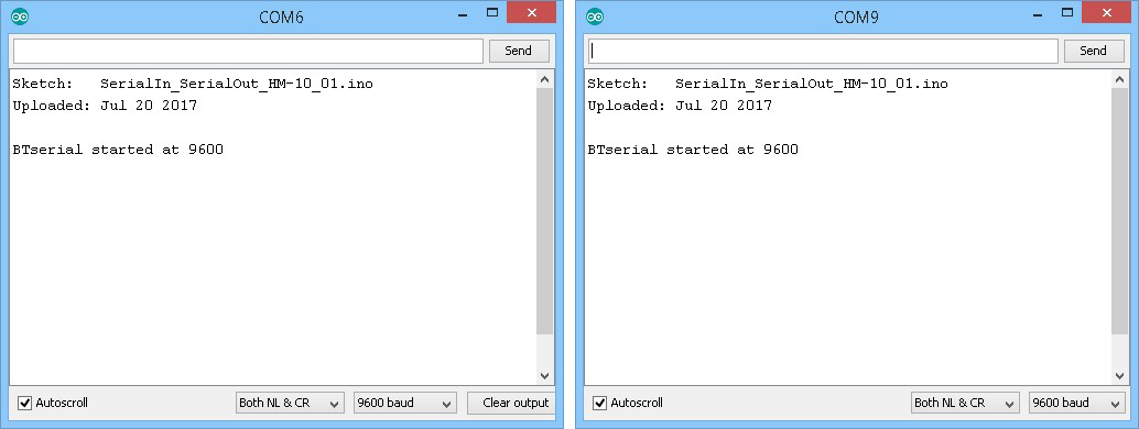
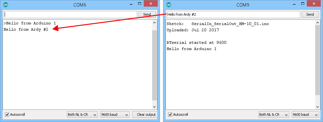
I am using 2 different Arduino IDEs. Version 1.82 as the main IDE and version 1.63 as the secondary IDE (I use the portable IDE). This gives me 2 serial monitors. The Arduino on COM6 is #1 and the Arduino on COM9 is #2.
HM-10 to HM-10 manual connection
To make a connection we:
Set the second module to Peripheral mode (the default setting),
Set the main module to manual start mode using “AT+IMME1”.
Then set the main module to Central mode with “AT+ROLE1”.
Then use “AT+CON” to connect. Of course you need to know the address of the second module which can be found using “AT+DISC?”.
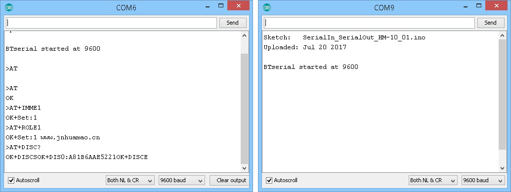
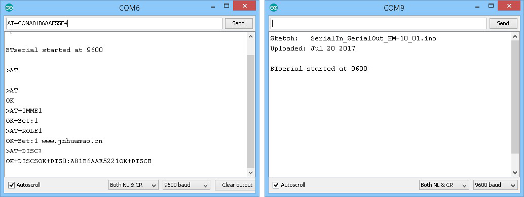
Now we have the address of the second HM-10 we can connect using the address or the found devices list index.
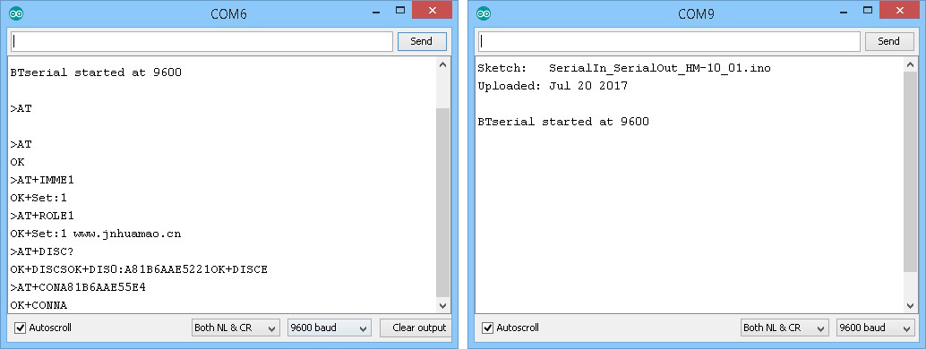
I am using the address and so the command is “AT+CONA81B6AAE5221”. You need to change the address to suit the modules you are using.
If the connection is successful we get “OK+CONNA” and the LEDs on the HM-10s stop flashing and become steady on.
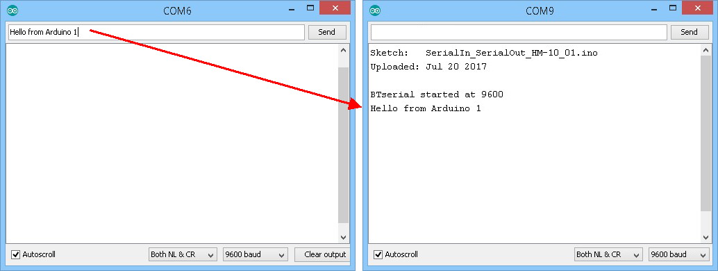
Now, everything entered in one serial monitor is transmitted to the other.
HM-10 to HM-10 automatic connection
The HM-10 can be set to automatically connect on start. No user intervention required.
When there are 2 or more modules and one is in Central mode it will search and connect to another HM-10. This is fully automatic and you have no control over which module it connects to although it would normally pick the one with the strongest signal. Of course, if there are only 2 modules it does not matter. When you have only 2 modules, set one to Peripheral mode and the other to Central mode. They should now connect automatically. Nothing else is required.
If there has been a previous connection, the device last connected to will take priority over other modules.
After you have made a manual connection, break the connection (cycle the power) and when ready enter “AT+IMME0” (this turns on auto connect). Then reset the module by either cycling the power or using the “AT+RESET” command. The modules should now auto connect even when there are addition HM-10s in range.
The “AT+IMME1” command stops the auto connect happening. Remember that you cannot use AT commands while there is an active connection (the commands are treated as data) (except “AT” which breaks a connection) so to enter AT commands you need to turn of the remote module and reset the Central one.
HM-10 to HM-10: Turning an LED on and off
We now try a remote control LED. This is a very simply example, when a button switch is pressed a remote LED comes on. When the button switch is released the LED goes out.
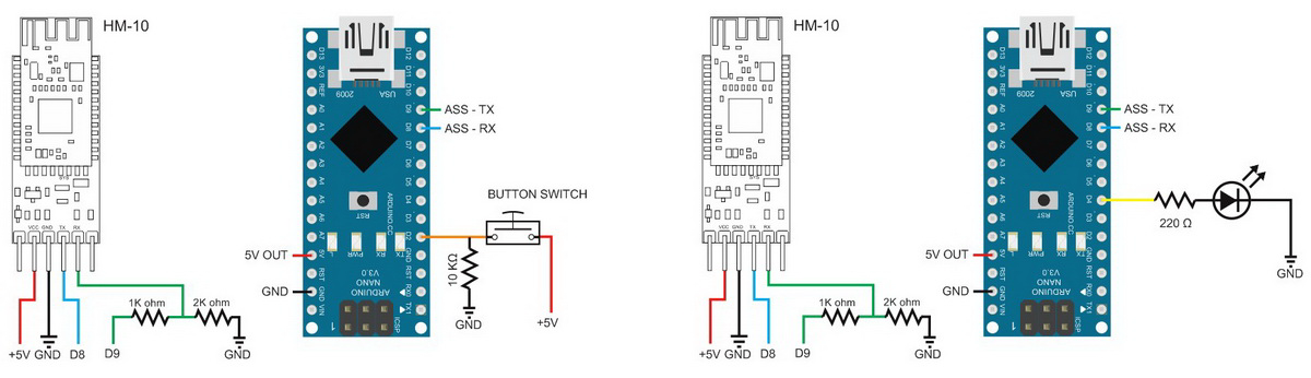
On Arduino #1 we add a button switch to D2 and on Arduino #2 we add a LED to D4.
The switch on Arduino #1 is pulled down with a 10K resistor. This means pressing the button switch makes the Arduino pin go LOW to HIGH.
The LED on Arduino #2 is connected inline with a 220 ohm resistor (330 ohm is also OK).
The sketch on the master Arduino uses 3 AT commands to set up the Central HM-10 and start the connection. These are the same commands we used in the manual connection example above.
BTserial.print("AT+IMME1" );
delay(1000);
BTserial.print("AT+ROLE1" );
delay(1000);
BTserial.print("AT+CONA81B6AAE5221" );
delay(1000);
This is not really the best solution but it works and it keeps the example easy to understand. Of course, if the HM-10 is already in Central mode and in manual start mode the first 2 commands are not required. The delays allow time for the replies. You could, if you wished, check for the correct reply before moving to the next command. Change the address to suit the modules you are using.
If you are using an older firmware you will need to add a “AT+RESET” command after the “AT+ROLE1”.
You could do away with these commands by using the auto-connect mode.
After this, the sketch checks the status of the pin connected to the button switch and if it has changed sends out 1 of 2 commands.
- LOW to HIGH. The button switch has been pressed so we want to turn on the LED. This is done by sending a “1” to the remote module.
- HIGH to LOW. The button switch has been released so we want to turn off the LED. This is done by sending a “0” to the remote module.
Note that we are sending ascii “1” and ascii “0” not the value 1 and the value 0.
// Very simple debouce.
boolean state1 = digitalRead(switchPin); delay(1);
boolean state2 = digitalRead(switchPin); delay(1);
boolean state3 = digitalRead(switchPin); delay(1);

if ((state1 == state2) && (state1==state3))
{
    switch_State = state1;

    if (switch_State != oldswitch_State)
    {
          if ( switch_State == HIGH) { BTserial.print("1" );  Serial.println("1"); }
          else                       { BTserial.print("0" );  Serial.println("0"); }

          oldswitch_State = switch_State;
    }
}
The secondary Arduino simply checks for a “1” or a “0” and if it finds one of them it either turns the LED on or turns the LED off.
void loop()
{
    // Read from the Bluetooth module and check if it is a command
    if (BTSerial.available())
    {
        c = BTSerial.read();

        // 49 is the ascii code for "1"
        // 48 is the ascii code for "0"
        if (c==49)   { digitalWrite(LEDpin,HIGH);   }
        if (c==48)   { digitalWrite(LEDpin,LOW);    }
        Serial.println(c);
    }

}
Here are the full sketches.
On the first Arduino we have HM-10_Example_01_simpleLED_Central.
// HM-10_Example_01_simpleLED_Central
//
//  Simple remote control using HM-10s: LED on. LED off
//
//
//  Pins
//  BT VCC to Arduino 5V out.
//  BT GND to GND
//  Arduino D8 (ASS RX) - BT TX no need voltage divider
//  Arduino D9 (ASS TX) - BT RX through a voltage divider
//

#include
AltSoftSerial BTserial;

byte switchPin = 2;
boolean switch_State = LOW;
boolean oldswitch_State = LOW;

void setup()
{
    Serial.begin(9600);
    Serial.print("Sketch:   ");   Serial.println(__FILE__);
    Serial.print("Uploaded: ");   Serial.println(__DATE__);
    Serial.println(" ");

    BTserial.begin(9600);
    Serial.println("BTserial started at 9600");
    Serial.println(" ");

    pinMode(switchPin, INPUT);

    // connect to the remote Bluetooth module
    BTserial.print("AT+IMME1" );
    delay(1000);
    BTserial.print("AT+ROLE1" );
    delay(1000);
    BTserial.print("AT+CONA81B6AAE5221" );
    delay(1000);

}

void loop()
{
    // Very simple debouce.
    boolean state1 = digitalRead(switchPin); delay(1);
    boolean state2 = digitalRead(switchPin); delay(1);
    boolean state3 = digitalRead(switchPin); delay(1);
    if ((state1 == state2) && (state1==state3))
    {
        switch_State = state1;

        if (switch_State != oldswitch_State)
        {
              if ( switch_State == HIGH) { BTserial.print("1" );  Serial.println("1"); }
              else                       { BTserial.print("0" );  Serial.println("0"); }

              oldswitch_State = switch_State;
        }
    }
}
On the second Arduino we have HM-10_Example_01_simpleLED_Peripheral.
// HM-10_Example_01_simpleLED_Peripheral
//
//  Pins
//  BT VCC to Arduino 5V out.
//  BT GND to GND
//  Arduino D8 (ASS RX) - BT TX no need voltage divider
//  Arduino D9 (ASS TX) - BT RX through a voltage divider
//

#include
AltSoftSerial BTSerial;

char c=' ';
byte LEDpin = 4;

void setup()
{
    Serial.begin(9600);
    Serial.print("Sketch:   ");   Serial.println(__FILE__);
    Serial.print("Uploaded: ");   Serial.println(__DATE__);
    Serial.println(" ");

    BTSerial.begin(9600);
    Serial.println("BTserial started at 9600");
    Serial.println(" ");

    pinMode(LEDpin, OUTPUT);
    digitalWrite(LEDpin,LOW);
}

void loop()
{
    // Read from the Bluetooth module and check if it is a command
    if (BTSerial.available())
    {
        c = BTSerial.read();

        // 49 is the ascii code for "1"
        // 48 is the ascii code for "0"
        if (c==49)   { digitalWrite(LEDpin,HIGH);   }
        if (c==48)   { digitalWrite(LEDpin,LOW);    }
        Serial.println(c);
    }

}
The above works well but what happens when you reset Arduino #1 when there is an Active connection? The LED comes on.
When you reset the Arduinos but not the HM-10s the connection remains active and the AT commands in the setup() function get sent as data and any “1”s in the data get recognised as LED Commands. There is a few things you can do to stop this happening.
- Before sending the AT commands, send a welcome message to see if there is an active connection. The remote device would reply to the message.
- Check the HM-10 STATE pin before sending the AT commands. The STATE pin is HIGH when there is a connection.
- Set the modules to auto connect and get rid of the AT commands. In my opinion this is the best option.
I leave this to you to implement.
If you want to know more about using serial data to control things, have a look at the Arduino Serial guides
In the next part I control an LED with just a HM-10, no second Arduino.
From Lars. Sent by contact form:
I’ve been following your tutorials for the HM-10 module, thanks a lot – they are great! I’m working on a project of my own, where I got communication going between a ATTiny and UNO. Smooth :D
But now I’m concerned with power consumption and want to throw the HM-10 module connected to the ATTiny in sleep mode between transmissions. The problem I’m having is tat while power is on, its connected to the UNO. While connected I’m not able to send AT commands it seems. Have you looked at this? Do you know how I can send AT commands to a HM-10 with a active connection when I want to sleep it to save power?
The default setting is once a connection has been made the AT commands are treated like data and get transmitted.
I presume the HM-10 connected to the ATTiny is the Peripheral , in which case you can set the Peripheral to allow AT commands over wireless with the AT+MODE command. You can then send the AT+SLEEP command remotely or use the AT+PWRM1 command to put the module to sleep when the connection is broken.
Hi Martyn,
Sorry to bother you, but can you please confirm whether you have tested sending AT+SLEEP remotely after configuring AT+MODE to allow AT commands wirelessly? In my case unfortunately, most other AT commands are working, except AT+SLEEP for some reason!
Take care.
Hi Martyn:
Great overview of the HM-10. Thanks for all your hard work putting it together!
Some random notes:
AT+DISI? when HM-10 is in central role scans for beacons in the area and returns all their info in ascii. A nice command for scanning the area.
AT+ROLE1: When you are switching the HM-10 to central role, I believe that you have to do an AT+RESET command afterwards in order to make the central role take effect.
AT+SCAN: As of firmware version 543, there is new scan duration command that you can use to make central role scans faster. The default is three seconds, which is quite slow, so it is nice to be able to change this to 1 second now.
Cheers!
Oops, forgot to mention AT+IMME…
To place HM-10 in central role, you need to do:
AT+ROLE1
then
AT+IMME1
then
AT+RESET
Al conectar con la aplicación Bluetooth Scan conecta sin ningun problema, pero, pero al tratar de agregarlo a la lista de dispositivo bluetooth, me indica que el dispositivo hm10 me aparese en el celular un mensaje que dice Vinculo rechazado por la tarjeta
Looks like a great overview of the HM-10.
Hopwever I have a problem! Every time I type AT into the serial monitor, it disconnects the HM-10 and does not respond with OK. I have triple checked the wiring and thats OK, so any idea why this would happen?
When there is a connection “AT” will break the connection. Normally it will not give any response or reply.
To get a response use “AT+NOT1”. Then when the connection is lost or broken the HM-10 will issue “AT+LOST”
The module does not disconnect now, but I don’t get any response from the Arduino serial port, as shown in your article.
Any idea how I can get it to respond?
Double check you have the correct connections; Arduino TX to HM-10 RX and Arduino RX to HM-10 TX.
Double check the baud rate.
Double check you have the correct pins defined in the sketch.
After double checking, run the sketch, open the serial monitor and cycle the power to the HM-10. At power on the HM-10 issues “www.jnhuamao.com” as a welcome message. If you do not get the message in the serial monitor recheck everything again.
Hi, thank you for the detailed tutorial.
I am trying to pair the HM-10 with another bluetooth device that requires me to provide a pin. I have successfully paid them, but have got now idea how I can get the HM-10 to send the pin (e.g. 512567) to this device.
Would you know how to do this? Thank you!
The best option, if you have access to the other device, is disable password pairing. If you can’t do this it should work by setting the PIN on the HM-10 to match the other device.
When pairing, the HM-10 will not ask for the PIN it will use its own PIN.
(Assuming the HM-10 is acting as the Central device)
Thank you, this is where it gets challenging because my peripheral device is a Hexiwear (www.hexiwear.com) wearable and each 6 digit pin it sends back is random. I have attempted to hack the hexiwear to always return the same pin and configure the HM-10 to use the same pin but there isn’t a response from the Hexiwear.
It seems that there needs to be some kind of command that lets the HM-10 send a pin code to the hexiwear when it asks for one.
In the raspberry pi, the command line utility that lets the central device provide the pin is bluetoothctl. I am not sure if there’s an equal in Aruduino, or have I gone beyond what a HM-10 could do.
Unfortunately the HM-10 does not have the facility to ask for a PIN, it just uses the one saved by the user, and so I doubt it is the right solution here.
You will probably need to look at other BLE modules where you have control over he Bluetooth side of things, such as those from Nordic, or an Arduino with built in BLE like the 101.
Thank you Martyn, this has been a good learning journey and your blog post helped a lot.
I learnt the possibilities and limitation of HM-10 and I am planning to approach my project differently. Instead of trying to connect to the hexiwear, I will probably try to build a prototype that uses the HM-10 with Arduino in the same way you connect 2 HM-10s.
Thank you again!
Hi jackson I also got same problem you are facing which is pairing hexiwear to HM-10, will you be able to connect it? is there any other way i could connect hexiwear to arduino using some other ble modues if can u please name them .
actually, Hexiwear has the mode that dont need to Auth and Pin, so just using HM-10’s AT command: AT+TYPE0 (not pin and auth). Then it can connect. However, I just stop at connecting step. I can not receive or send data from HM-10. I am finding solution
thank you for your detailed description of the HM-10 BLE module, especially the characteristic description
i would have a few questions :
after speed testing with a cortex m0+ (nxp lpc824 30 MHz) with dedicated speed test firmware and either a QT 5.9.1 speed test app on kubuntu 16.04 or an android speed test app on nexus 7 2013, my tests so far have discovered that the hm-10 can at best handle 1 byte / ms in and out
if i compare this to a regular bt-spp based module it’s by a factor of 5 slower, 5 bytes / ms at 57.6 kBd (max speed at this baud rate) … maybe faster if i up the baud rate
what i’m after is more inforrmation on the hm-10 :
hm-10 min “connection interval” time … the ble specs defines it as 7.5 ms … what’s the hm-10 data ???
hm-10 max “number of pkgs x-mit per connection event” … one or more ???
since i need more throughput, but would like to stay with low cost chinese devices i was wondering if u had a chance to evaluate the hm-16, which is also cortex m0 based and claims to be faster
HM-10/11 speed is about 2KB/seconds
HM-16/17 speed is about 3-8KB/seconds
as well as lower power
HM-10/11 in automatic sleep mode 50~400uA
HM-10/11 in active mode 8.5mA
HM-16/17 in automatic sleep mode 50~1200uA
HM-16/17 in active mode 6.5mA
any ideas on your end would be highly appreciated
cheers Klaus
just found this as by-packed with the bluetooth41_en.zip which partially answers one of my questions
actually it was part of the spec sheet, and i missed it
HM-10/11 CC2540/1 V538
=======================================================================
1. Add AT+COMI command, config Minimum Link Layer connection interval
para1 value: 0 ~ 9; Default: 3(20ms);
0: 7.5ms; 1: 10ms; 2: 15ms; 3: 20ms; 4: 25ms; 5: 30ms; 6: 35ms; 7: 40ms; 8: 45ms; 9: 4000ms
2. Add AT+COMA command, config Maximum Link Layer connection interval
para1 value: 0 ~ 9; Default: 7(40ms);
0: 7.5ms; 1: 10ms; 2: 15ms; 3: 20ms; 4: 25ms; 5: 30ms; 6: 35ms; 7: 40ms; 8: 45ms; 9: 4000ms
3. Add AT+COLA command, config Link Layer connection slave latency
para1 value: 0 ~ 4; Default: 0;
4. Add AT+COSU command, config Link Layer connection supervision timeout
para1 value: 0 ~ 6; Default: 6(6000ms);
0: 100ms; 1: 1000ms; 2: 2000ms; 3: 3000ms; 4: 4000ms; 5: 5000ms; 6: 6000ms;
5. Add AT+COUP command, switch slave role update connection parameter
para1 value 0, 1; Default: 1(Update on);
0: Update off; 1: Update on;
i get about 1 byte per ms and if i think about right that the hm-10 has a default “connection interval” of 21 ms and one pkg contains a max of 20 bytes, then this would be the 1 byte / ms … just a thought
now the hm-10 has an at cmd of AT_COMI which is supposed to change the link layer min connection interval down to 7.5 ms (ble min specs) one would think that this might get the speed up by 3
well … not so fast … my hm-10 rev is 527, which does not support this cmd and the upgrade to a newer rev has bricked the only one i had soldered into my regular test setup … all others are in dedicated hw and i might have some somewhere, but that’s it for today
thanks to fasttech.com i have now a few hm-16’s on order … what a day
maybe this helps others to get a better understanding of the bandwidth limits of ble … assuming my thought are correct
cheers Klaus
I haven’t done a lot with bench marks on the HM-10 and have only really used them with Arduinos which adds its own speed limits. When I need better through put or better control I use a different module.
It wouldn’t hurt to contact Jinan Huamao. I have found them fairly responsive to emails and I have found them helpful : support@jnhuamao.cn
Is there a way to limit an HM-10 slave device to only connect to a specific master device ?
My HM-10 devices are v605.
Not really sure, however, you may be able to achieve something similar with the TYPE command.
Look at TYPE:3 (Auth and bonded)