Updated on 06.08.2016
Controlling an Arduino over Bluetooth from Android using App Inventor 2
Here is an example of controlling the Arduino over Bluetooth using a HC-06 bluetooth module and an Android app. The example uses an Arduino Nano but other Arduinos will work just as well. A HC-05 module can be used stead of the HC-06.
The Android app was created in app inventor and the aia file can be downloaded at the bottom of the page.
The app has:
– buttons for turning LEDs on and off
– sliders for controlling an RGB LED
– navigation keypad
– command buttons
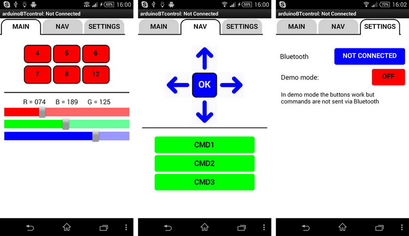
The app has a demo mode where the buttons work but commands are not sent via Bluetooth.
Arduino Setup
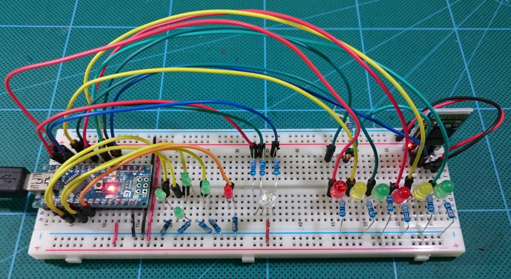
Connect the LEDs
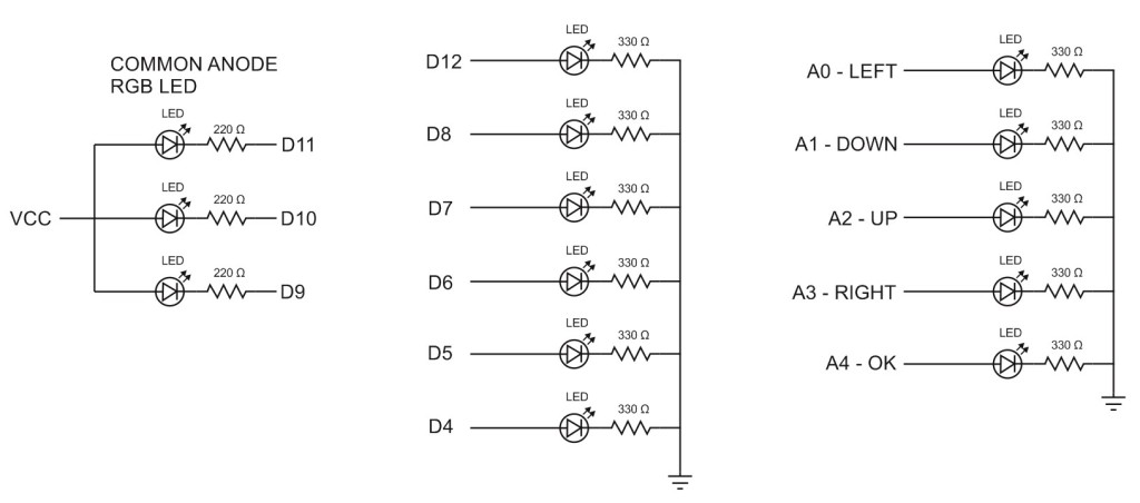
I have used a common anode RGB LED. If you use a common cathode the common pin will need to go to ground rather than VCC and the sliders will be backwards.
I have used 220ohm and 330ohm resistors because these are what I had but any resistor from 220hm to around 480ohm will be OK. Just be aware that the higher the resistor value the duller the LED will be.
Connect the Bluetooth module
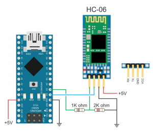
Arduino D2 (software serial RX pin) to BT module TX pin
Arduino D3 (software serial TX pin) to BT module RX pin via a voltage divider
Gnd to Gnd
BT VCC to the Arduinos 5v out
Although the BT module can accept an input voltage of 3.6 to 6v, the data pins are 3.3v only. This means you should not connect the Arduino D3 pin (TX) directly to the BT modules RX pin. The Arduino will read the 3.3v coming from the BT TX pin as HIGH so this can be connected directly. The Arduinos RX pin, which is 5v, needs to be brought down to 3.3v before connecting to the BT modules TX pin and a simple way of doing this is with a voltage divider mode from 2 resistors.
The BT module will take a maximum current of 40mA so it is safe to power it from the Arduinos 5v out pin.
I am using the Bluetooth modules default settings:
– Baud rate = 9600
– Name = HC06
Pairing
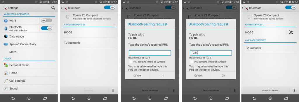
Before you can connect the app to the HC-06 you need to pair it with the Android device.
Power on the HC-06. The LED will blink rapidly.
Open Settings on the Android device and select Bluetooth.
If your device does not auto-scan you will need to manually scan for available Bluetooth devices. The HC-06 should appear in the list.
Select the HC-06. You will be asked for the pin. The default pin is “1234”.
The HC-06 modules name may include the mac address; a series of hexadecimal numbers.
After pairing the HC-06 you can connect to it from within the arduinoBTcontrol app.
Connecting to the Arduino
Start the Arduino, the LED on the bluetooth module should blink rapidly.
Open the arduinoBTcontrol app on you Android device,
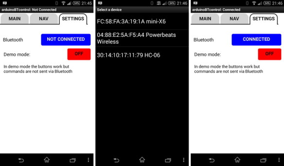
Go to the settings screen.
Tap the bluetooth button, this brings up a list of paired devices.
select the HC-06.
After the Arduino is connected the bluetooth button will change to say Connected and the LED on the bluetooth module will stop blinking and turn on.
Controlling the Arduino
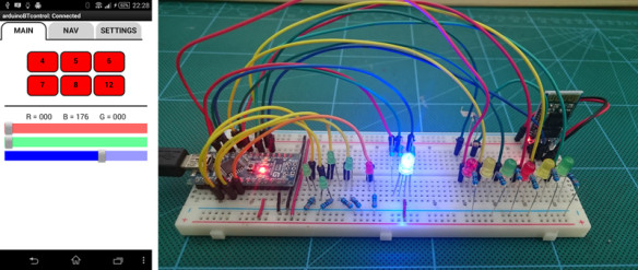
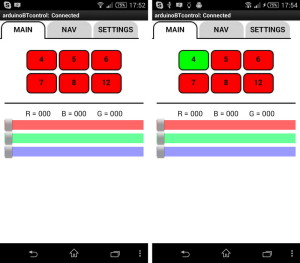
After you are connected, go back to the MAIN screen and either tap a button or move the sliders.
The LED buttons toggle on and off. The first tap will turn the LED on, the second will turn it off.
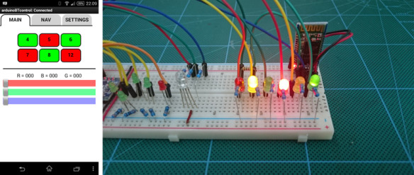
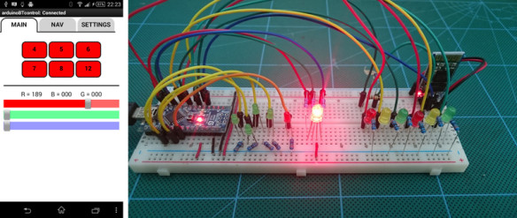
The sliders transmit their value as soon as they start moving. Although you can move them before the Arduino is connected they will not send any data until after a connection is made.
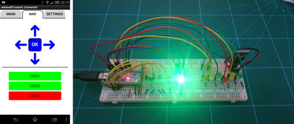
The NAV screen contains a navigation keypad and 3 command buttons.
The direction buttons on the keypad are active while ever they are being pressed, the OK btn sends a signal as soon as it is pressed (it doesn’t wait for the user to lift their finger. The command buttons send unique commands and use normal button clicks.
The command buttons activate one of 3 sequences on the Arduino. When a command button is clicked, it will turn red and become inactive until the sequence is completed. When the sequence is finished the button will return to green and a ready sound is played. Command buttons cannot be pressed while a sequence is active. For the 3 commands buttons, the Arduino sends a finished/acknowledgement signal back to the Android app. It is this signal that triggers the command button being reset
Command 3 cycles the RGB LED through the 3 different colours.
Arduino Sketch
The Android app sends ascii codes, enclosed in start and end tags, to the Arduino. The Arduino recieves the data through the serial connection with the BT module.
The sketch and app can be downloaded at the bottom of the page.Comments is the sketch should explain what is happening.
The main parts are the recvWithStartEndMarkers() and the parseData() functions. recvWithStartEndMarkers() checks the received data for a start marker, the [ character, and when found starts to copy the received data to buffer/ variable called receivedChars[] until it finds the end marker, the ] character.
parseData() checks receivedChars[] buffer for commands and when it finds one it performs a certain action such as turn an LED on or off.
/* * arduinoBTcontrolUpdated * Bluetooth remote control from an Arndroid app * Download the Android app from www.martyncurrey.com * * Written using IDE 1.6.3 * * Some of the below code is not very elegant but it should * be easy to follow what it does. * * Pins * 2 Software serial - RX * 3 Software serial - TX * 4 LED * 5 LED * 6 LED * 7 LED * 8 LED * 9 RGB LED RED PIN * 10 RGB LED GREEN PIN * 11 RGB LED BLUE PIN * 12 LED * 14 LED * 15 LED * 16 LED * 17 LED * 18 LED * */ // DEBUG // when debug is true, debug messages are sent to the Arduino serial monitor boolean debug = true; #include <SoftwareSerial.h> SoftwareSerial BTserial(2,3); // RX | TX // BT module is connected to pins D2 and D3. // Arduino RX (pin D2) to BT TX. // Arduino TX (pin D3) to BT RX. Needs a voltage divider to bring the voltage down to 3.3V // max length of received command is 20 chrs not including the \0 character const byte numChars = 21; char receivedChars[numChars]; boolean newData = false; unsigned int red = 255; unsigned int green = 255; unsigned int blue = 255; byte UPpin = 16; byte DOWNpin = 15; byte LEFTpin = 14; byte RIGHTpin = 17; byte OKpin = 18; void setup() { pinMode(12, OUTPUT); pinMode(8, OUTPUT); pinMode(7, OUTPUT); pinMode(6, OUTPUT); pinMode(5, OUTPUT); pinMode(4, OUTPUT); pinMode(11, OUTPUT); pinMode(10, OUTPUT); pinMode(9, OUTPUT); // Common anode RGB lED, 255 is off. // If using a common cathod RGB lED then remove the next 3 lines. analogWrite(9, red); analogWrite(10, green); analogWrite(11, blue); pinMode(14, OUTPUT); pinMode(15, OUTPUT); pinMode(16, OUTPUT); pinMode(17, OUTPUT); pinMode(18, OUTPUT); Serial.begin(9600); if (debug) { Serial.println("arduinoBTcontrol Ver 2.0"); } if (debug) { Serial.println("For use with the arduinoBTcontrol Android app"); } if (debug) { Serial.println(" "); } // The Bluetooth module used has a default baud rate of 9600 // This can be changed but be aware software serial doesn't like fast baud rates BTserial.begin(9600); } // All the loop function is does is check to see if there is any data from the Bluetooth module // and if there is see if it is a command void loop() { if (BTserial.available() > 0) { recvWithStartEndMarkers(); } if (newData) { parseData(); } } /* **************************************** * Function parseData * checks receivedChars[] for valid commands then acts accordingly * * passed: * * global: * receivedChars[] * newData * * Returns: * * Sets: * newData * */ void parseData() { newData = false; if (debug) { Serial.println( receivedChars ); } // BUTTON // B001ON - B for button. 001 is the button number. ON = on // B001OF - B for button. 001 is the button number. OF = off if (receivedChars[0] == 'B' ) { int tmp = convertToNumber( 1 ); if ( receivedChars[4] == 'O' && receivedChars[5] == 'N' ) { digitalWrite(tmp,HIGH); } if ( receivedChars[4] == 'O' && receivedChars[5] == 'F' ) { digitalWrite(tmp,LOW); } } // BUTTON // RGB SLIDER // Trrrgggbbb if ( receivedChars[0] == 'T' ) { // For a common anode RGB LED take the value away from 255. // If using a common cathod RGB led then use: // red = convertToNumber( 1 ); // green = convertToNumber( 4 ); // blue = convertToNumber( 7 ); red = 255 - convertToNumber( 1 ); // convertToNumber converts the ascii numbers to a numeric value green = 255 - convertToNumber( 4 ); // the number is brackets the the start posotion of the value blue = 255 - convertToNumber( 7 ); analogWrite(9, red); analogWrite(10, green); analogWrite(11, blue); } // RGB SLIDER // NAVIGATION // NUON - N = navigation. U for UP. ON for on // NUOF - N = navigation. U for UP. OF for off if ( receivedChars[0] == 'N' ) { if ( receivedChars[1] == 'U' ) // UP { if ( receivedChars[2] == 'O' && receivedChars[3] == 'N' ) { digitalWrite(UPpin,HIGH); } if ( receivedChars[2] == 'O' && receivedChars[3] == 'F' ) { digitalWrite(UPpin,LOW); } } if ( receivedChars[1] == 'D' ) // DOWN { if ( receivedChars[2] == 'O' && receivedChars[3] == 'N' ) { digitalWrite(DOWNpin,HIGH); } if ( receivedChars[2] == 'O' && receivedChars[3] == 'F' ) { digitalWrite(DOWNpin,LOW); } } if ( receivedChars[1] == 'L' ) // LEFT { if ( receivedChars[2] == 'O' && receivedChars[3] == 'N' ) { digitalWrite(LEFTpin,HIGH); } if ( receivedChars[2] == 'O' && receivedChars[3] == 'F' ) { digitalWrite(LEFTpin,LOW); } } if ( receivedChars[1] == 'R' ) // RIGHT { if ( receivedChars[2] == 'O' && receivedChars[3] == 'N' ) { digitalWrite(RIGHTpin,HIGH); } if ( receivedChars[2] == 'O' && receivedChars[3] == 'F' ) { digitalWrite(RIGHTpin,LOW); } } if ( receivedChars[1] == 'K' ) // OK { if ( receivedChars[2] == 'O' && receivedChars[3] == 'K' ) { digitalWrite(OKpin,HIGH); delay(75); digitalWrite(OKpin,LOW); } } } // NAVIGATION // COMMAND if (strcmp ("CCMD1",receivedChars) == 0) { for ( byte Count = 1; Count <= 15; Count++) { digitalWrite(4,HIGH); delay(100); digitalWrite(4,LOW); digitalWrite(12,HIGH); delay(100); digitalWrite(12,LOW); } sendOK(1); } if (strcmp ("CCMD2",receivedChars) == 0) { for ( byte Count = 1; Count <= 5; Count++) { digitalWrite(4,HIGH); delay(100); digitalWrite(4,LOW); digitalWrite(5,HIGH); delay(100); digitalWrite(5,LOW); digitalWrite(6,HIGH); delay(100); digitalWrite(6,LOW); digitalWrite(7,HIGH); delay(100); digitalWrite(7,LOW); digitalWrite(8,HIGH); delay(100); digitalWrite(8,LOW); digitalWrite(12,HIGH); delay(100); digitalWrite(12,LOW); } sendOK(2); } if (strcmp ("CCMD3",receivedChars) == 0) { red = 255; green = 255; blue = 255; for(int red = 255; red >0; red--) { analogWrite(9, red); delay (5); } for(int red = 0; red < 256; red++) { analogWrite(9, red); delay (5); } for(int green = 255; green >0; green--) { analogWrite(10, green); delay (5); } for(int green = 0; green < 256; green++) { analogWrite(10, green); delay (5); } for(int blue = 255; blue >0; blue--) { analogWrite(11, blue); delay (5); } for(int blue = 0; blue < 256; blue++) { analogWrite(11, blue); delay (5); } sendOK(3); } } // function recvWithStartEndMarkers by Robin2 of the Arduino forums // See http://forum.arduino.cc/index.php?topic=288234.0 /* **************************************** * Function recvWithStartEndMarkers * reads serial data and returns the contents between a start marker and an end marker. * * passed: * * global: * receivedChars[] * newData * * Returns: * * Sets: * newData * receivedChars * */ void recvWithStartEndMarkers() { static boolean recvInProgress = false; static byte ndx = 0; char startMarker = '['; char endMarker = ']'; char rc; if (BTserial.available() > 0) { rc = BTserial.read(); if (recvInProgress == true) { if (rc != endMarker) { receivedChars[ndx] = rc; ndx++; if (ndx >= numChars) { ndx = numChars - 1; } } else { receivedChars[ndx] = '\0'; // terminate the string recvInProgress = false; ndx = 0; newData = true; } } else if (rc == startMarker) { recvInProgress = true; } } } /* **************************************** * Function convertToNumber * converts 3 ascii characters to a numeric value * the 3 characters are inside receivedChars[] * startPos is the position within receivedChars[] if the first ascii character * * passed: * * global: * receivedChars[] * * Returns: * an int value * * Sets: * */ int convertToNumber( byte startPos) { unsigned int tmp = 0; tmp = (receivedChars[startPos]-48) * 100; tmp = tmp + (receivedChars[startPos+1]-48) * 10; tmp = tmp + receivedChars[startPos+2]-48; return tmp; } // send a simple finished code to the app void sendOK(int val) { BTserial.print("OK");BTserial.print(val);BTserial.print("#"); if (debug) { Serial.print("OK");Serial.print(val);Serial.println("#"); } } |
Android App
The Android app is written is MIT’s app inventor 2 and the aia file can be downloaded at the bottom of the page. Here are the key parts of the app.
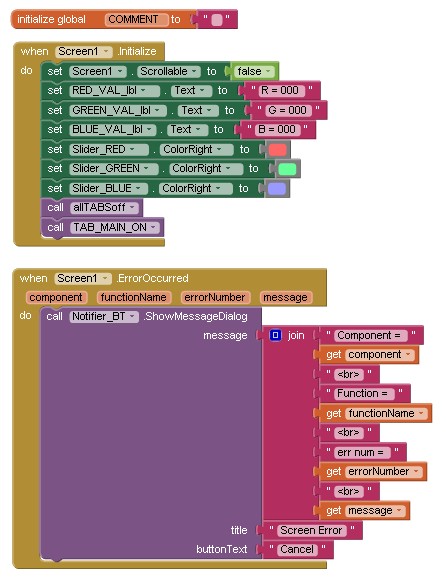
When the app first starts Screen1.Initialize is called. This sets the slider value labels and changes the sliders ColorRight colours. The colours I wanted are not available in the designer and need to be set in the blocks.
Sceen1.ErrorOccurred block traps any system errors and displays then in a pop up message box.
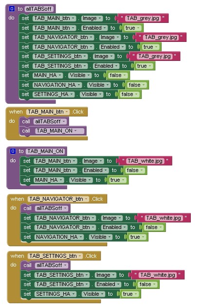
The different screens, MAIN, NAV, and SETTINGS, are not really different screens. The tabs are buttons and when clicked they display or hide certain containers. When the MAIN tab is clicked, the MAIN container is displayed and the NAV and SETTINGS containers are hidden. I use this method to overcome a problem when using Bluetooth. In Android, each screen is treated like a separate app and using traditional screens means you cannot use a Bluetooth connection across different screens.
The logic is very simple. I turn off all tabs and then turn on the one I want. The code for the MAIN tab is in a procedure so that I can call it from the Screen1.Initialize function.
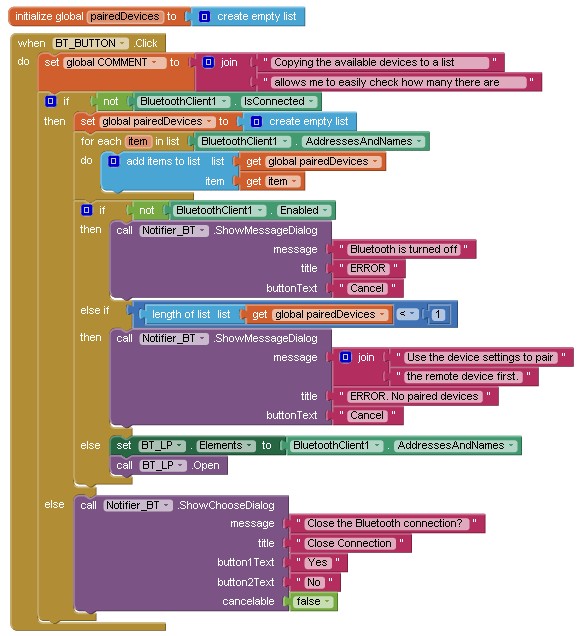
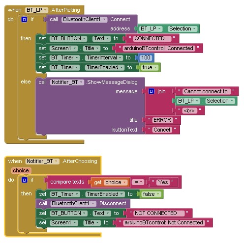
The Bluetooth connection is initiated when the user clicks the Bluetooth button on the SETTINGS screen. When the button is clicked the app checks that Bluetooth is turned on and then the available paired devices are copied to a list, the length of the list is then checked to make sure we have at least one device. If we have, a list picker is opened showing the paired devices. When the user selects one of the devices the BT_LP.AfterPicking function is called.
If the app is already connected the user is asked if they would like to close the connection.
If the connection is successful the button text is changed to CONNECTED and the BT_Timer is started. If the connection fails then an error message is displayed.
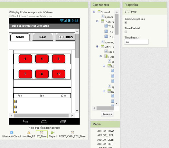
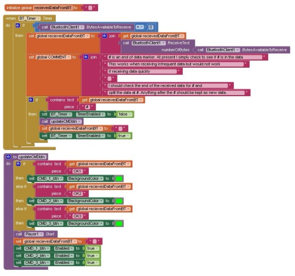
BT_Timer is used to check for incoming data. The timer frequency is set in the designer at 200ms, this is 5 times a second which is sufficient for this example. For more complex apps you would probably need a faster timer.
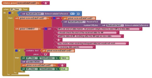
When the timer fires the BT_Timer.Timer function is called. This checks to see if there is any new data and if there is append it to a buffer. The buffer is stored in the receivedDataFromBT variable. The buffer is then checked to see if we have certain markers which in this case is a # character. If the app finds the end of data marker the updateCMDbtn function is called.
This app is a basic example and the only part that uses a call back from the Arduino are the 3 COMMAND buttons on the NAV page. Therefore using a simple end of data marker is acceptable. For more complex communication it would be better to use start and end markers. Later i will have a more advanced guide using start and end markers.
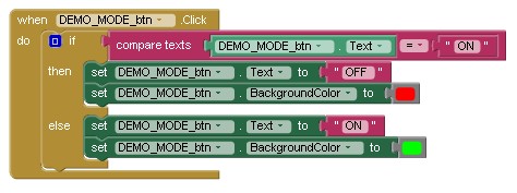
A demo mode allows the user to try the app without having a Bluetooth connection. In non demo mode the buttons do not work when there is no connection and clicking a button generates a “Bluetooth is not connected” error.
Demo mode is turned on and off on the SETTINGS page. The Demo mode button toggles between ON and OFF every time it is clicked.
Pin Buttons
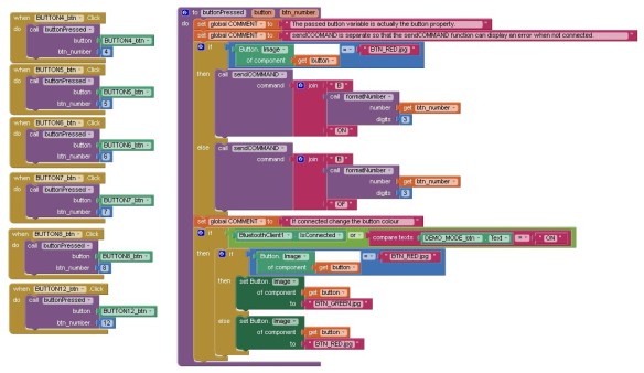
On the MAIN page, the buttons correspond with pins on the Arduino. clicking one of the buttons toggles the button ON and OFF and also sends the corresponding command to the Arduino.
When a button is clicked the button property and the button number is passed to the buttonPressed function. Here the command to either turn on or turn off the LED is created and passed to the sendCommand function and the button background image is changed.
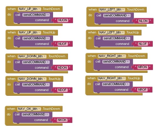
The Navigation buttons send a command as soon as they are touched (touch down) and also when the button is released (touch up). This basically sends a start and stop signal to the Arduino.
The OK button acts differently. It only sends a command on touch down. In this way the Arduino can react as soon as it is pressed and does not need to wait for the user to lift their finger.
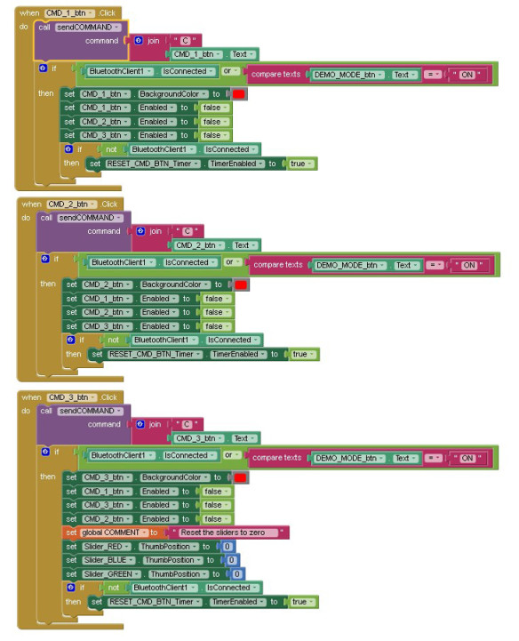
The command buttons send a CMD command to the Arduino, turn red and then wait for the Arduino to say it is finished. While waiting the command buttons are inactive.
You can see that the 3 functions are very similar and they could easily be merged in to one function.
The BT_Timer starts running when a connection is made. Even if the command buttons are never clicked, the timer still keeps checking for data.
When the Arduino receives one of the CMD commands and has performed the corresponding function it replies with a “I am finished” message in the form of “OK1#”, “OK2#”, or “OK3#”. When the app receives one of these messages it resets the command buttons.
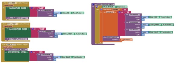
The final controls are the sliders. Sliders generate events when ever the slider position changes and so they can generate a lot of data. The slider command is created by joining the values from each slider together in the form Trrrgggbb. The values are converted to ascii before sending. This means the format is fixed, it is always 3 characters per colour. If speed is not that important using ascii to send data is very convenient and very robust.
Download
The zip file contains the Arduino sketch and the app inventor aia file.
Martyn,
This is a very helpful tutorial!
Can you please add the .aia file to the download .zip, so that we have the blocks to work with?
Thanks!
Steve,
I have added the aia file to the download
thank you very much
Thanks for the reply to my last comment. Reading through everything but I cant figure out what part I would use in the sketch to send a return value. Also how I will use AI2 to receive that value.
Hi Shane,
inside the Arduino sketch it is the sendOK() function that sends the acknowledgement signal back to the Android app.
The data is either OK1##, OK2##, or OK3## depending on which commands was received. the “##” is an end of data marker.
void sendOK(int val)
{
BTserial.print(“OK”);BTserial.print(val);BTserial.print(“##”);
if (debug) { Serial.print(“OK”);Serial.print(val);Serial.println(“##”); }
}
In the Android app I have a timer that keeps checking for data received via Bluetooth. Look at the following blocks
BT_Timer.Timer – this handles the timer event
thereIsBTdata – checks to see if there is any data from Bluetooth
getDataFrom_BT – gets data from Bluetooth
As mentioned before, this is a very basic implementation but it should be suitable for use with an “all off” signal”.
OK I got the app figured out for the block but the sketch is giving me troubles.
void parseData()
{
newData = false;
if (debug) {
Serial.println( receivedChars );
}
if (receivedChars[0] == ‘O’ && receivedChars[1] == ‘N’ ) {
digitalWrite(LEDpin, HIGH);
BTserial.print(“High”);BTserial.print(“#High#”);
if (debug) { Serial.print(“High”);Serial.println(“#High#”);
}
if (receivedChars[0] == ‘O’ && receivedChars[1] == ‘F’ ) {
digitalWrite(LEDpin, LOW);
BTserial.print(“Low”);BTserial.print(“#Low#”);
if (debug) { Serial.print(“Low”);Serial.println(“#Low#”);
}
}
this is where i need to add the sendok. If the LED is high send high if its low send low.
If this is for the auto close then you do not need to worry about the LED state. Just before the Arduino closes down send a “I’m closing now” signal to the app. When the app receives this signal the app should reset all the buttons to off. Since you know the Arduino is closing you don’t even need to check the button state in the app, just set all to off.
The parseData() function only checks the received commands and is not the right place to add the code. Assuming you have a function or code to handle the shut down then the extra code should go there.
It might be worth learning a little bit more about serial. Take a look at http://forum.arduino.cc/index.php?topic=288234.0. I found this very helpful.
if you have not already, register on the Arduino Forum – http://forum.arduino.cc/. You can get a lot more help with code there and the format is better for answering these kinds of questions.
Hi Martyn, great material – many thanks for sharing!! I started with your post: “Arduino with HC-05 (ZS-040) Bluetooth module – AT MODE”, and was able to work with my BT modules, received past week (they are marked as GW-040). Then I continued with “Turning a LED on and off” and I’m glad to have the app working perfectly after editing a little detail in the corresponding .aia file. Now I’m in this post but the app is stuck in the SETTING tab when I pair the BT module. Really appreciated if you can share the .aia to try to figure out my problem. I saw you have replied before that the .aia file is already in the .zip, but it is not right now. Thanks in advance!!
Not sure what keeps happening to the aia file. One minute its there and the next it isn’t…. Have created a separate download for it. See above.
Why did you need to edit in the LED on/off app? If you found a problem please let me know so I can update the app.
I haven’t come across the GW-040 boards. What firmware to they have? Do they have the same breakout board at the zs-040?
how do u do the app inventor
Hi Martyn,
Great tutorial!
I would like to ask one question.
I cannot see “NAV” screen after I click it (kind of stuck?).
I also cannot see “start and end markers” & “acknowledgement” menus at setting screen but only bluetooth menu.
Is this a device problem?
Do you have any idea why?
Regards,
Brian
I have updated the post. The new sketch and aia file can be downloaded at the bottom of the post.
Hello Sir Martyn, I’m currently working right now about our school project. I’m done with master/slave and connecting BT from phone to arduino sending commands.I can control only one HC-05 slave at the moment using my own made application using Android Studio. Here lies the problem sir, when i pair, link and bind two HC-05 it works but when I use my phone application to connect to one of the HC-05 (so that i can use my phone to send command) it couldn’t connect because they have already connected with each other. Do you have any idea how to do this sir?
Bluetooth devices can connect one at a time only. If you want to use a third device you must disconnect the existing connection first.
Hi
Your tutorial is really helpfull.
I am beginneer to this meter.
I want to make an app using app inventor.
I want to add 4 LED or more ON and OFF . and also adding 2 or more servo at a same app .
so what shall i do .
Please help me.
Thank you ..
Go through the app inventor tutorials, start with https://www.martyncurrey.com/turning-a-led-on-and-off-with-an-arduino-a-hc-06-and-android/
Excellent site , je vous remercie pour ces explications formidables …Bonne continuation
Excellent site , Merci et bonne continuation