There is now an updated and more detailed post. See Controlling a Solenoid Valve from an Arduino. Updated.
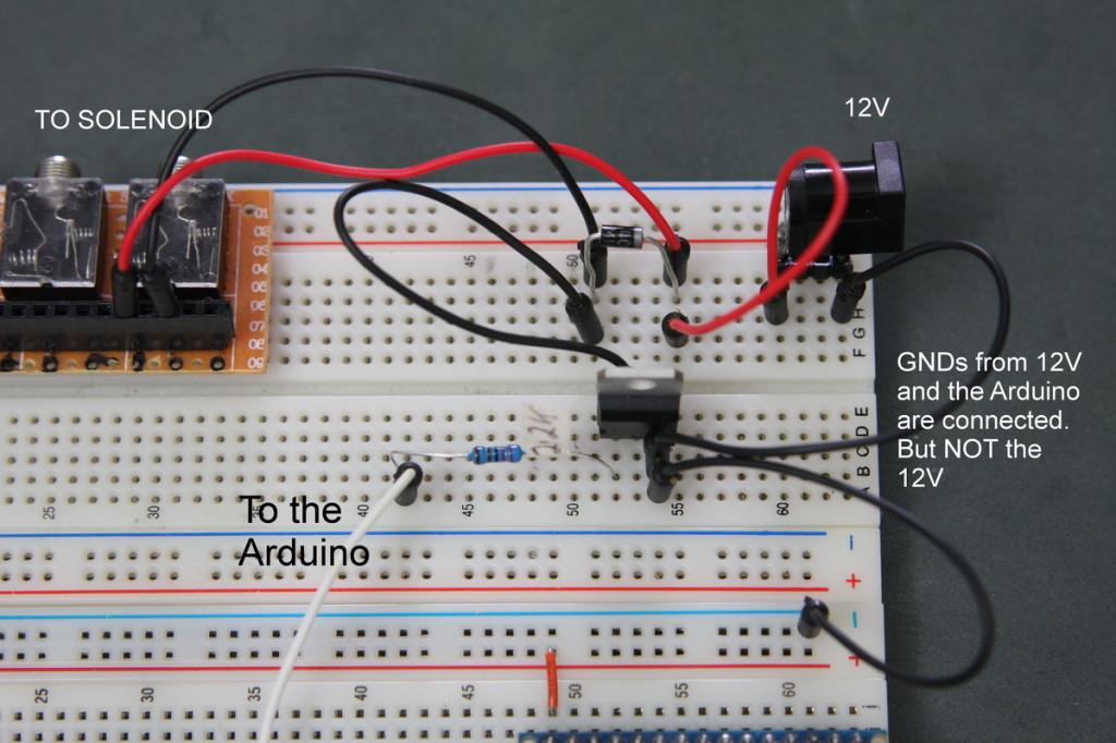
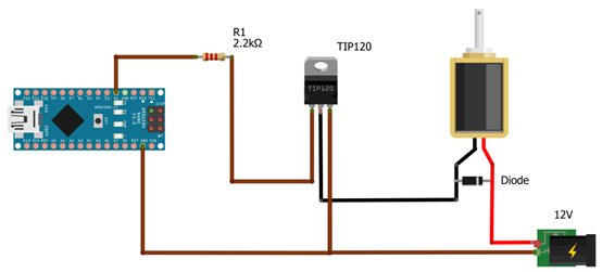
Using the Arduino to control the solenoid valve is simply a case of setting a pin high for the appropriate amount of time. There is, however, a caveat, the solenoid works at a different voltage to the Arduino and you cannot directly connect the two. In this case a TIP120 transistor is used as a bridge.
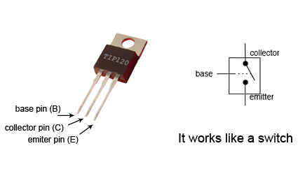
The TIP120 allows a small dc voltage (from the Arduino) to switch a larger dc voltage (12V to the solenoid). It can be thought of as a switch, applying a current to B allows current to flow between C to E.
Connecting a solenoid to an Arduino
The diode (a 1N4007 in this case) connected to the solenoid allows current to flow only in one direction. When the current is turned off the solenoid tries to continue the current. This can fry the Arduino. The diode feeds this current back in to the solenoid until it is dissipated.
Here is the circuit on a breadboard.

You can get more information about connecting a solenoid at
http://playground.arduino.cc/Learning/SolenoidTutorial
http://bildr.org/2011/03/high-power-control-with-arduino-and-tip120/


I’m asking what software you have used to create the diagram resuming the connections.
Thanks
It’s Fritzing: http://fritzing.org/home/
I was wondering if you could post the code that you used for the arduino?
To open the solenoid you just need to set the Arduino pin connected to the TIP120 HIGH. It is the same as turning on a LED which you can see in the Blink sketch.
Thanks
Can you please send by e-mail me the code for this script Controlling a Solenoid Valve from an Arduino | Martyn Currey or please inform me in detail about this script?
Can you send me the arduino code which you coded to control the pneumatic solenoid valve using arduino
Can you post the arduino code which is used to control the pneumatic solenoid valve..?
Follow the Arduino Blink example but change the pin to the one connected to the valve.
Hi Martyn,
I have tried your example but it’s not working with my water pump.
I’m using Arduino, 2.2K resistor, TIP120, water pump (3.5-9V 1-3W), 9V AC adapter.
Everything connected as on your diagram.
* when I connect pump directly to 9V, it’s working
* when connect through transistor, it’s not. However when I connect multimeter instead of water pump, I see that transistor is opened.
Do you have any idea, why it’s not working?
Hi Oleg,
Is the 9V AC adaptor powering the water pump? The TIP120 can only be used for DC, not AC. If the pump is AC then look at using a relay instead. The Arduino would turn the relay on and off and the relay would allow current to the pump.
When picking a relay be careful about how much current it will draw. The Arduino can safety provide 40 mA only. Many relays will draw more than this.
Sorry, adapter is DC :)
A few of things I would suggest.
1. Redo all the wires and check all the connections.
2. remove the Arduino. Connect the wire that goes to the Arduino digital pin directly to 5V (still needs the 2.2K resistor). If the pump works then the problem is with the Arduino, either the hardware or more likely with your sketch.
3. Test the TIP120 with an LED. Replace the pump with an LED (inline with a 1K ohm resistor). See if you can get the LED to turn on and off. Once you have confirmed the TIP120 is working you can work on getting the pump to work.
Ok, I have connected diode + 1K resistor instead of pump. Diode is working fine.
But pump sometimes works, but sometimes not. When I connect it directly to DC, it works. Then I connect it to my pcb, it works few times (3-7 times) and then it stops, but still I can see new “Pump!” messages in serial monitor. Then again I need to connect it directly to DC to make it live.
Here is my code:
http://paste.ofcode.org/3XyMUzF35hJbuBC2YYiyf3
I am also having a similar problem, but have tried all your troubleshooting ideas. The valve opens when it is connected directly to the AC/DC Convertor. The valve won’t open when connected through the PCB. I had a different solenoid valve (Adafruit) and it did work with this circuit. The new one I have pulls more current, but my AC/DC Convertor is rated for that. I can’t find another problem. Any ideas?
Probably my DC adapter is too weak (300mA). I have connected my pcb + pump to 9V battery and it’s working without problems. Need to find better adapter :)
Glad you found the problem.
Thanks! :)
I am using a 220v ac solenoid valve.Can i power it in the same way(using a 12v dc)??
I don’t think so. I am not qualified to advise on 220V and you would get better advice from the Arduino forum. http://forum.arduino.cc/
Sorry I can’t be more helpful.
You want to use a relay for anything mains voltage.
Hi Martyn,
Thank for the tutorial.
I just have a question. Why did you choose to use a transistor instead of a MOSFET?
I have a large bag of TIP120s, 121s, and 122s :-)
A suitable mosfet can also be used.
Im trying to use my arduino UNO to send a +5V signal to a mosfet to drive a 24V solenoid. i know that i need a diode across the solenoid to protect it. What i don’t know is how to pick the right mosfet. I know that i needs to be logic compatible. My power supply is 24VAC 750mA. the in rush current of the solenoid is 0.35A @ 24 VAC. The holding current is 0.23A @ 24VAC.
I want you to answer this question. This is my problem too.
Have a look at the updated guide. Link at the top of the article.
I generally use IRLZ44N and IRL540N. The L stands for logic level which in this case is 5V. There are many alternatives. The main thing to search for is logic level 5V, check that the max voltage and current are more than you actually need and that the mosfet has a low RDSon at 4v or 5 v.
If you are using a 3v arduino then look for logic level 3V.
This circuit need exactly TIP120? Is it possible if I am using TIP42C?
What was the source of 12V? did you use batteries or plug adapter?
I use a wall wart but batteries will work the same.
Nice circuit. However, I would like to add a led between arduino digital pin and transistor, so to easily watch pin status in the board. Thank you :)
I’m a software guy, so electronics is not my strengh. What if I would want to control several solenoids with an Arduino and several shift registers (74HC595) how would the circuit change with a led between shift register and transistor? Thanks again, your doc has helped me already a lot.
Have a look at the dropController circuit at http://www.dropcontroller.com.
If you want to add LEDs to show when the valve is open look at the original dropController circuit at http://www.dropcontroller.com/dropcontroller-2/
I don’t have anything written up for the 74HC595 but there are lots of guides on line and if you have specific questions ask on the Arduino forum at http://forum.arduino.cc/index.php. Somebody there will be able to help.
Sorry for this basic question.
What is the purpose of 2.2K resistor?
Thank you
The resistor is used to limit the current. Without it the transistor would try to draw more current than it really requires which would likely damage the Arduino, the transistor, or both.
I googled for TIP120s, and it seems there’s a whole bunch of varieties of them, like NPN or BJT etc. If there’s no real difference between them, can I just get the cheapest one?
There is only 1 type of TIP120, there are through, many kinds of TIP devices and while TIP120s are BJTs (Bipolar Junction Transistors) so are almost all other transistors.
There are 2 types of Bipolar Junction Transistors, NPNs and PNPs. The TIP120 is a NPN type Darlington transistor.
This means the TIP120 is both an NPN and a BJT.
I’m wondering what’s that 12V in the picture? how it drive a 12V to the circuit while it’s not connected to anything?
It is 12v in to drive the solenoid.
I mean is that little black thing gives you 12V directly? or it will be connected to something else?
It is a connector that connects to a 12v power supply.
hello!
what is the arduino code you used for this connection?
regards,
Can 9v battery used to power 12v solenoid valve? or is current too low from battery?
Does it have to be from a legit 6-12vdc range with more current rating of 1A or greater?
it depends on the valve.
I have various 12v solenoid valves that I use for water drop photography and all can be activated from a lower voltage but they then react slower than normal.
The power supply amp has to be enough to satisfy the value. In general. You need to check the requirements of your actual valve.
Generally u are using TIP120 as switch in the above ckt u placed the switch across the load and gnd but when i tried by keeping the switch between the source and load it is not working can be explain why it is?
Thanks in advance
The TIP120 is a NPN transistor so it is better to have it on the LOW side (GND side). To have a transistor on the HIGH side (vcc side) use a PNP transistor such as TIP125, TIP126, or TIP127.
I didn’t know that solenoids worked at different voltages. Thanks for mentioning how transistors can be used to control them. My husband is looking into solenoids; I will pass this post on to him so that he knows how to use them.
You not knowing that solenoids can operate using different voltages doesn’t instil a lot of confidence in your company ;-)
Good job dude
please send code to control solenoidal valve using ardiuno and gsm800a
Does it work with a TIP3055 transistor?
Hello everyone,
I would like to operate a pneumatic cylinder with the help of Arduino, solenoid valve and ultrasonic sensor. Can you please help me to make connections.
The working is want is when Ultrasonic sensor find something in its way at the same time solenoid valve should work to operate pneumatic cylinder .
Hope you understand what I am talking about.
I am waiting for help.
Thanks
I want to operate a 24 v solenoid through Arduino nano and have a 24v supply, will there be change in TIP120 or diode IN4007.
Hello sir, I got inspired by this project, it’s too cool and decided to do one, so I purchased all the mentioned components but they have some different ratings, such as-
Solenoid valve= AC220-240V; 50/60Hz and
Transistor= TIP122
So,is it OK to use them and if yes then how.
THANKYOU..
Hello,
The valve is AC power, you need a DC version. If possible return it and get either a 12V DC or 24V DC valve.
If you are unable to return it you may, depending on the make, be able to change the coil to a DC coil.
The TIP122 is DC only. Do not use with AC.
hi , how can i find the Solenoid Valve in arduino library please ?
There isn’t a library for this. Controlling a valve is simply a case of turning a pin on and off.
good morning sir,
I’m doing my final year project, i need your help to guide sir,
I’m trying to use the solenoid valve for allowing oxy-hydrogen gas..
is it possible..?
if yes how that solenoid valve can be controlled by arduino?
please reply sir..
I can’t recommend a valve but most valves have decent data sheets that will show what they can be used with and what pressures.
When paired with the correct switching device, ike a transistor, mosfet, or relay, the Arduino can probably control most valves.
If I want to add a momentary push button for control. Should I do it on the positive side or negative or should I just connect to gnd+digit pins on arduino using its internal pull-up resistance?
If you want to add an on/off switch which is read by the Arduino then either method; pulled up or pulled down is fine.
I tend to use an external resistor and pull the line down but this is often regarded as a hobbyist approach (I like that the pin is pulled down at start).
Using the Arduino’s internal pullup resistor means the logic is flipped but required one less component. Thisd does mean that the pin is in a non determined state while the Arduino boots though.