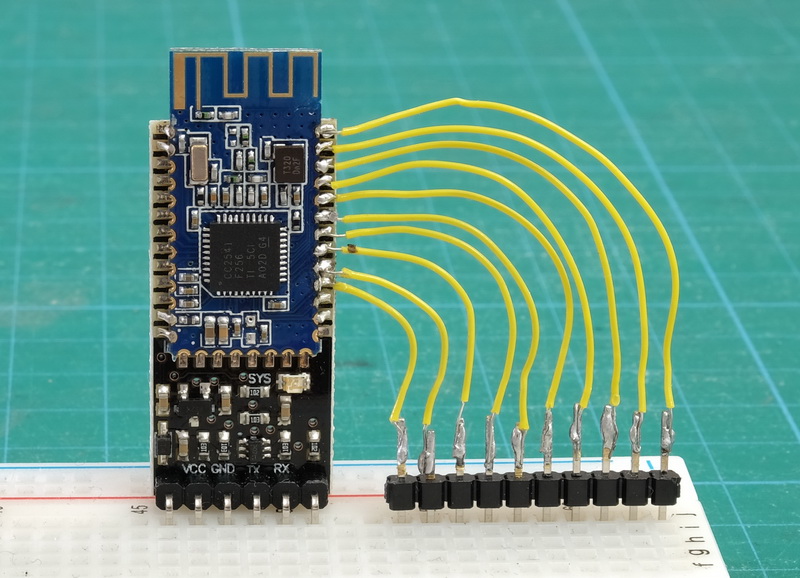
The HM-10 has 10 pins that can be user controlled, a couple are input only, the others can be input or output. Unfortunately, the pins we can control are not available on the breakout board so we need to attach a connection directly to the actual HM-10 (the small daughter board).
Pin function
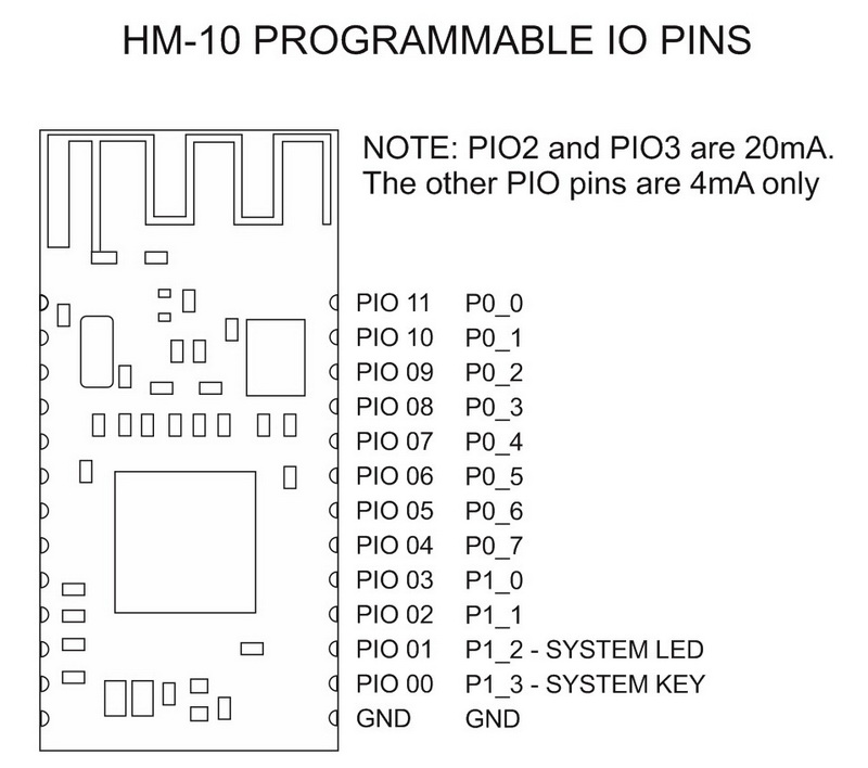
The pins we can use are PIO-2 to PIO-11(B).
PIO pins can be used as input or output:
| HM-10 PIN | Pin Function |
| PIO2 | OUTPUT / PWM OUTPUT |
| PIO3 | OUTPUT |
| PIO4 | INPUT / ADC / OUTPUT |
| PIO5 | INPUT / ADC / OUTPUT |
| PIO6 | INPUT / ADC / OUTPUT |
| PIO7 | INPUT / ADC / OUTPUT |
| PIO8 | INPUT / ADC / OUTPUT |
| PIO9 | INPUT / ADC / OUTPUT |
| PIOA (10) | INPUT / ADC / OUTPUT |
| PIOB (11) | INPUT / ADC/DS18B20/DHT11 / OUTPUT |
NOTE: PIO-2 and PIO-3 can supply up to 20mA. PIO-3 to PIO-11 are only designed to supply 4mA.
HM-10 pin control AT commands
AT+PIO[pin][0/1]
Set the output of a pin HIGH or LOW.
pin = pin number from 2 to B
0/1 = 0 for LOW 1 for HIGH
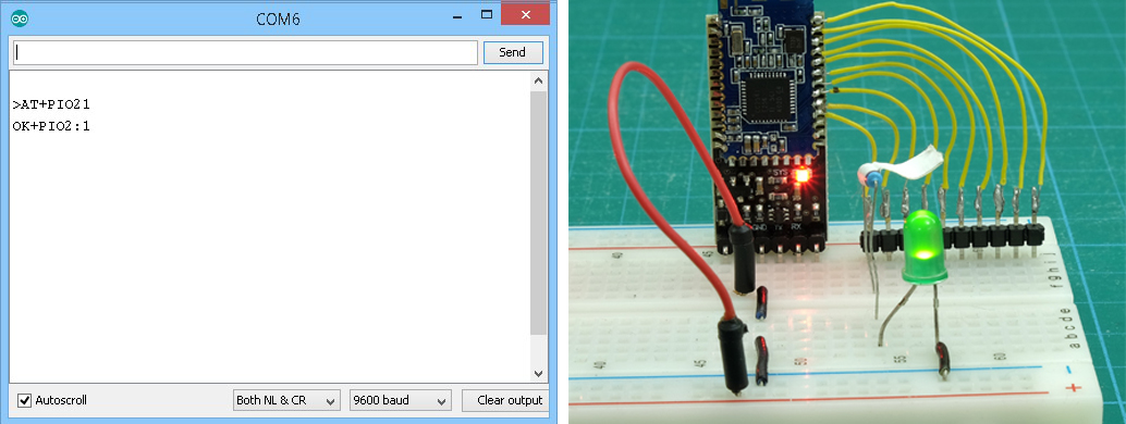
To set pin PIO-2 to HIGH we use “AT+PIO21” and to set it LOW use “AT+PIO20”
AT+PIO2x
Pin PIO2 can be used for PWN output.
x = a value from 0 to 9.
- AT+PIO20 = LOW
- AT+PIO21 = HIGH
- AT+PIO22 = 100ms PWM
- AT+PIO23 = 200ms PWM
- …
- AT+PIO29 = 800ms PWM
Note: The frequency is equal on off. So AT+PIO21 sets the pin to 100ms HIGH and then 100ms LOW.
There are different ways to read the pin state, either by reading each pin individually or reading them all at one time.
AT+PIO[pin]?
Read the current pin status.
pin = pin number from 2 to B.
To read the status for pin PIO2 use AT+PIO2? Returns the status in the form “OK+PIO2:0” OR “OK+PIO2:1”.
0 = LOW and 1 = HIGH.
AT+COL??
Note the double question marks.
Query the state of pins PIO2 to PIOB (11).
Returns a single byte in the form “OK+Col:00” to “OK+Col:FF” that represents the current state of the pins PIO4 to PIOB (11). Bits 7 to 0 are mapped to pin POI4 to PIOB.
| PIN | 4 | 5 | 6 | 7 | 8 | 9 | A | B |
| BIT | 7 | 6 | 5 | 4 | 3 | 2 | 1 | 0 |
AT+PIO??
Read the status of all PIO pins one time.
Returns 4 bytes in the form “OK+PIO?:0000” to “OK+PIO?:03FF”. The last 3 digits are mapped to PIO0 to PIOB; this mean 3FF is 001111111111 or all HIGH. Pins PIO0 and PIO1 (the first 2 digits) are used by the system and there return 0.
Pins PIO4 to PIOB can be used for analogue input.
AT+ADC[pin]?
Read the voltage on a give pin.
pin = PIO pin from 4 to B.
returns the actual voltage in the form of a 3 digit float.
To read the voltage on pin PIOA (10) use “AT+ADCA?”, returns “OK+ADCA:2.80” when 2.8v is applied to the pin and “OK+ADCA:0.00” when the pin is LOW or no voltage is applied.
AT+CYC[freq]
Set the rate that the pin state registers (inside the CC2541) are updated (querying pins actually queries the register not the pin).
freq = the frequency to update in seconds and is a 2 digit number 00 to 99.
The command will only accept a 2 digit number, “AT+CYC01” rather than “AT+CYC1”.
AT+CYC??
Notice the double question marks.
Query the current frequency
Returns a 2 digit value in the form “OK+Get:00” TO “OK+Get:99”
The default is 10 seconds.
Pin states can also be set when the HM-10 is first powered on with AT+BEFC and also when a connection is established with AT+AFTC.
AT+BEFC[pinValues]
Set PIO pin status before a connection / on power.
pinValues = a 3 digit number, 000 to 3FF, that is mapped to pins PIO0 to PIOB.Remember that PIO0 and PIO1 are used by the system and only the pins PIO2 to PIOB are available for use.
To set all the pins (PIO2 to PIOB) HIGH set BEFC to “001111111111” which is “3FF” with “AT+BEFC3FF”.
Pins set using BEFC can be changed later using AT+PIOxv.
AT+AFTC[pinValues]
Set pin status after a connection is established.
pinValues = a 3 digit number, 000 to 3FF, that is mapped to pins PIO0 to PIOB (same as AT+BECF). Remember that PIO0 and PIO1 are used by the system and only the pins PIO2 to PIOB are available for use.
To set pin PIO2 HIGH when a connection is established set AFT to “001000000000” or “200” with “AT+AFTC200”
Controlling the pins while the HM-10 is connected to a microprocessor, like an Arduino, doesn’t really make sense, after all it is probably better to use an Arduino pin. Where this can be useful is where the HM-10 is being used stand-alone.
HM-10 Peripheral mode: remote pin control
The PIO pins on a remote Peripheral mode HM-10 can be controlled remotely. We can do this because the HM-10 allows the Peripheral device to receive AT commands over wireless and the pins can be controlled with AT commands. When the HM-10 is used remotely and the AT commands are received over wireless, the pin control commands work a little differently. Here we need to to set either MODE1 or MODE2.
PIO pins can be used as input or output:
| HM-10 PIN | MODE1 | MODE2 |
| PIO2 | OUTPUT / PWM OUTPUT | OUTPUT / PWM |
| PIO3 | OUTPUT | OUTPUT |
| PIO4 | INPUT / ADC | OUTPUT |
| PIO5 | INPUT / ADC | OUTPUT |
| PIO6 | INPUT / ADC | OUTPUT |
| PIO7 | INPUT / ADC | OUTPUT |
| PIO8 | INPUT / ADC | OUTPUT |
| PIO9 | INPUT / ADC | OUTPUT |
| PIOA (10) | INPUT / ADC | OUTPUT |
| PIOB (11) | INPUT / ADC/DS18B20/DHT11 | OUTPUT |
NOTE: PIO-2 and PIO-3 can supply up to 20mA. PIO-3 to PIO-11 are only designed to supply 4mA.
To tell the HM-10 we want to control the user PIO pins remotely we use “AT+MODE1” and “AT+MODE2”.
AT+MODE1
Set the PIO pin control mode.
PIO2 and PIO3 to output and pins PIO4 to PIOB to input.
AT+MODE2
Set the PIO pin control mode.
PIO2 to PIOB as input.
In MODE1 only pins PIO2 and PIO3 are set to output. This means AT+PIOxv only works for these 2 pins. If you try to set one of the other pins the HM-10 will not respond, or, depending on the firmware, it may break and then re-establish the connection.
HM-10 stand-alone: Remote control an LED using MODE2
As a simple example to get started we will turn an LED on and off. First we will do this manually using AT commands and the serial monitor and once we have this working we can add a button switch to the Arduino and have the sketch do the work.
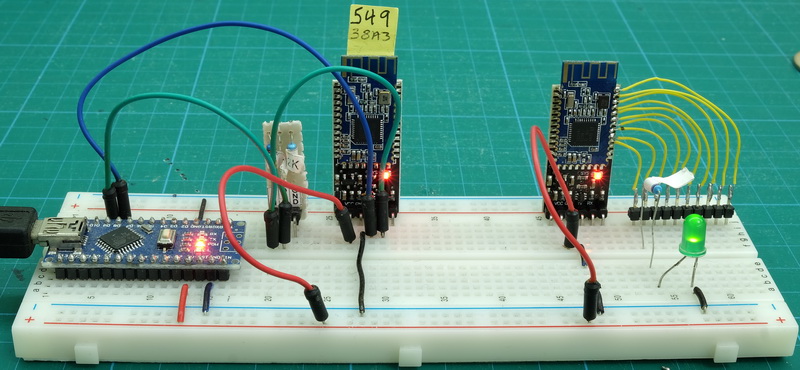
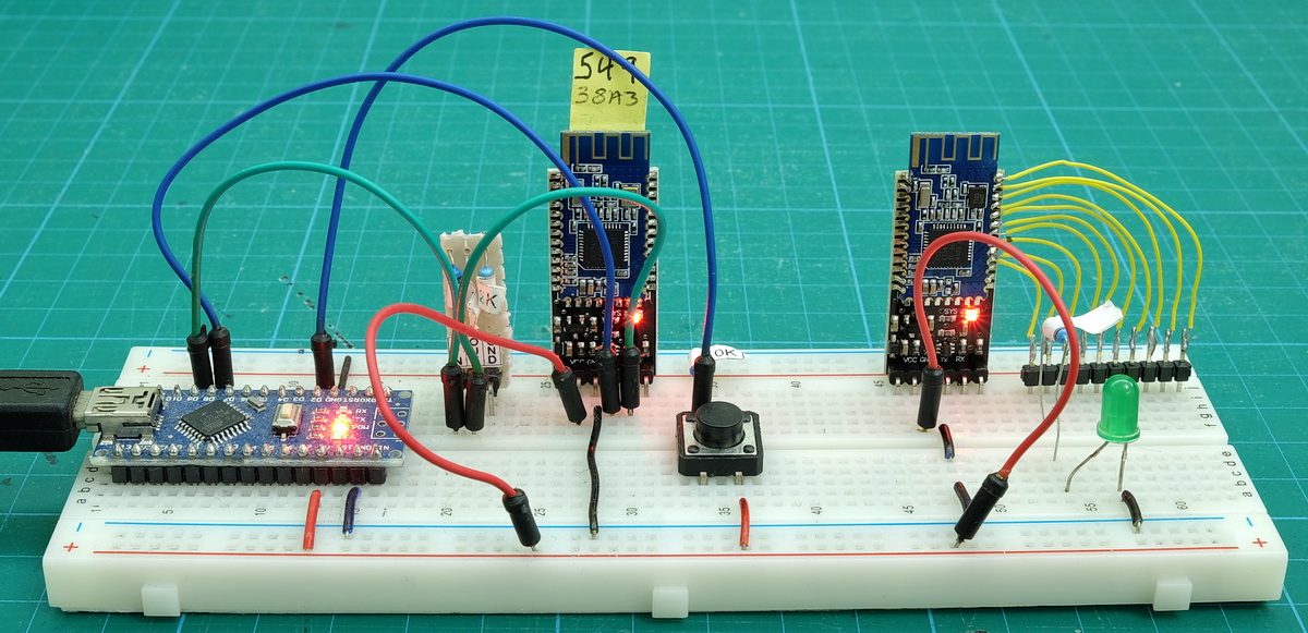
Circuit
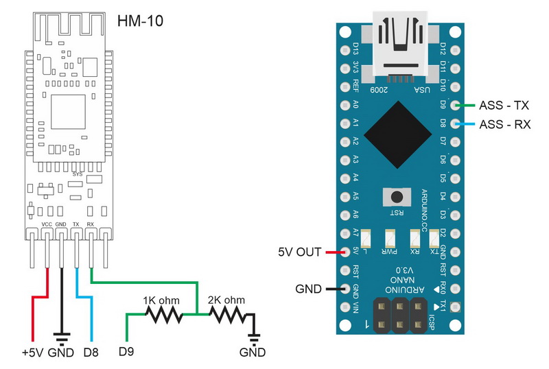
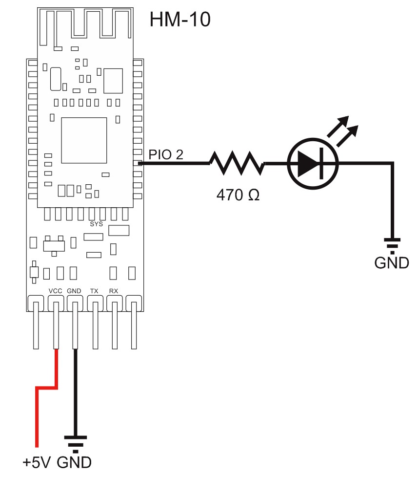
The Master or Central HM-10 is connected to an Arduino. The Peripheral or Slave HM-10 has an LED+resistor connected to PIO-2. I have the remote HM-10 powered from the Arduino but in practise you’d use a separate power supply such as a battery.
Manual Process
After putting the circuit together upload the following sketch. The sketch uses the AltSoftSerial library which will need to be installed in to the Arduino IDE before you can compile the sketch.
//  SerialIn_SerialOut_HM-10_01
//
//  Uses hardware serial to talk to the host computer and AltSoftSerial for communication with the bluetooth module
//
//  What ever is entered in the serial monitor is sent to the connected device
//  Anything received from the connected device is copied to the serial monitor
//  Does not send line endings to the HM-10
//
//  Pins
//  BT VCC to Arduino 5V out.
//  BT GND to GND
//  Arduino D8 (SS RX) - BT TX no need voltage divider
//  Arduino D9 (SS TX) - BT RX through a voltage divider (5v to 3.3v)
//

#include
AltSoftSerial BTserial;
// https://www.pjrc.com/teensy/td_libs_AltSoftSerial.html


char c=' ';
boolean NL = true;

void setup()
{
    Serial.begin(9600);
    Serial.print("Sketch:   ");   Serial.println(__FILE__);
    Serial.print("Uploaded: ");   Serial.println(__DATE__);
    Serial.println(" ");

    BTserial.begin(9600);
    Serial.println("BTserial started at 9600");
}

void loop()
{
    // Read from the Bluetooth module and send to the Arduino Serial Monitor
    if (BTserial.available())
    {
        c = BTserial.read();
        Serial.write(c);
    }


    // Read from the Serial Monitor and send to the Bluetooth module
    if (Serial.available())
    {
        c = Serial.read();

        if (c!=10 & c!=13 )
        {
             BTserial.write(c);
        }

        // Echo the user input to the main window. The ">" character indicates the user entered text.
        if (NL) { Serial.print("\r\n>");  NL = false; }
        Serial.write(c);
        if (c==10) { NL = true; }
    }
}
There are a few things we need to.
1. Set the Peripheral mode module to accept AT commands over wireless
2, Set the main module to Central mode
3, Make a connection
4, Use AT+PIO commands to turn the remote LED on and off
Set up the Peripheral mode device
To set up the Peripheral device we first need to tell it to accept AT commands over wireless. Unfortunately you cannot do this over wireless so we need to use wires and UART. You can use a computer with a usb-to-serial adapter or an Arduino and the serial sketch. I am using an Arduino and the serial sketch.
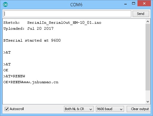
Commands
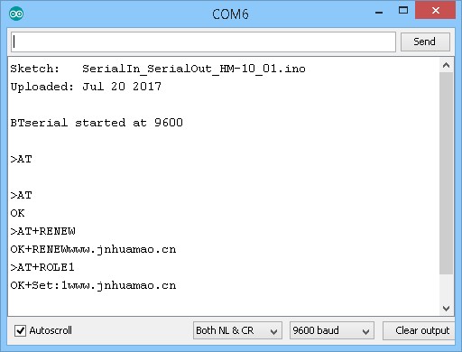
- AT
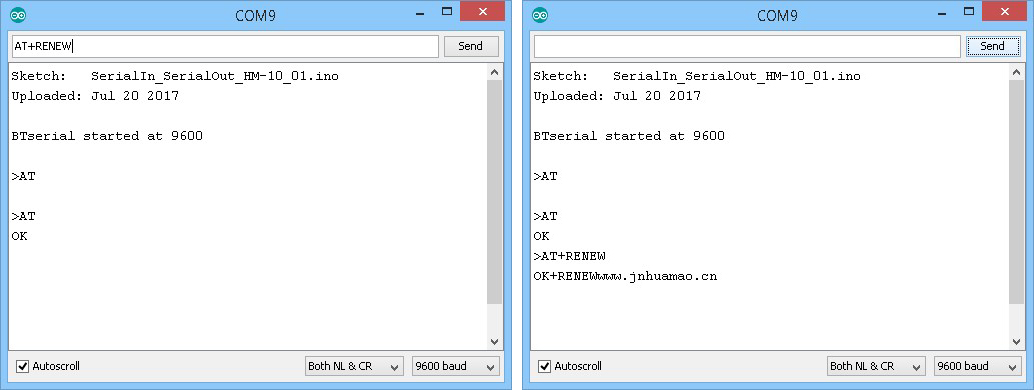
- AT+RENEW
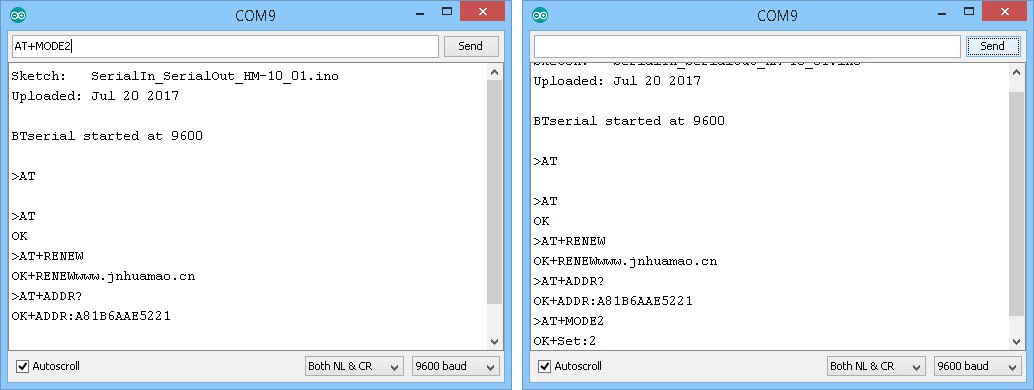
- AT+MODE2
Confirm the connections are correct and the HM-10 is responding by using “AT” and then revert the HM-10 to default settings with “AT+RENEW”. HM-10s default to Peripheral mode.
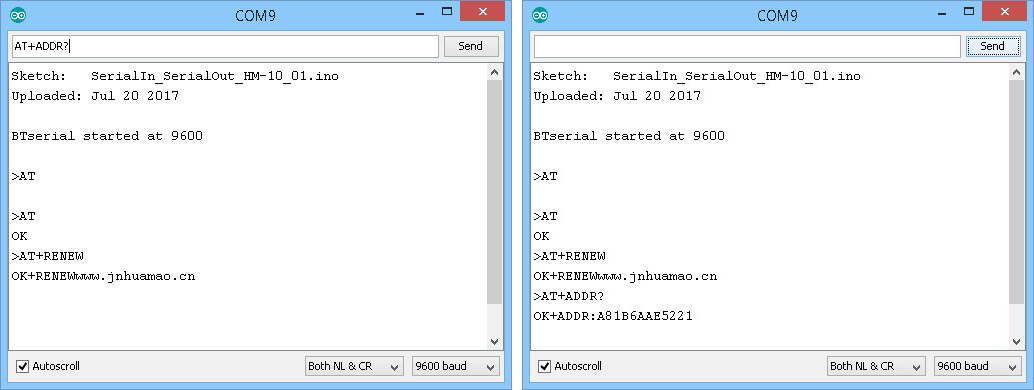
Get the address. You need this when connecting the devices together.
Set Mode to 2. This tells the HM-10 to accept AT commands over wireless.
The module with address A81B6AAE5221 is now set to Peripheral mode and set to allow AT commands over wireless.
We can now move the module and add an LED to PIO 2.
Set up the Central mode device
After swapping the HM-10s we are ready to set up the Central mode module.
Commands
- AT
- AT+RENEW
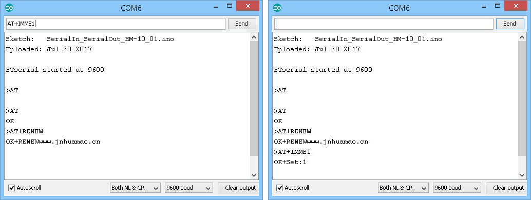
- AT+IMME1
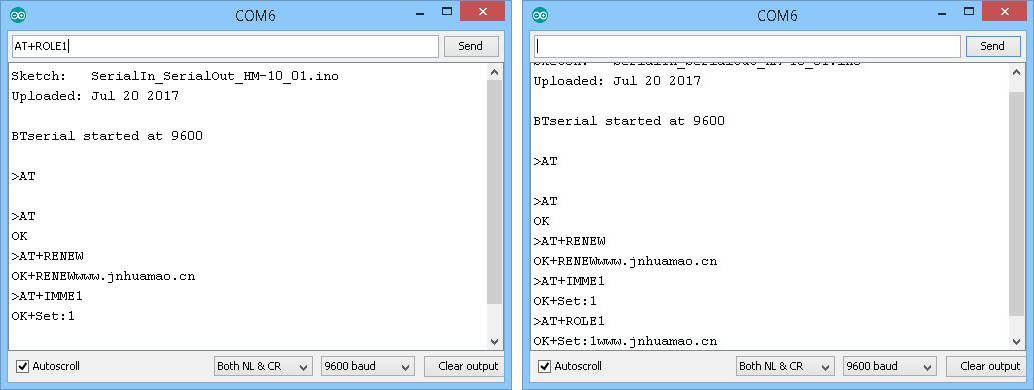
- AT+ROLE1
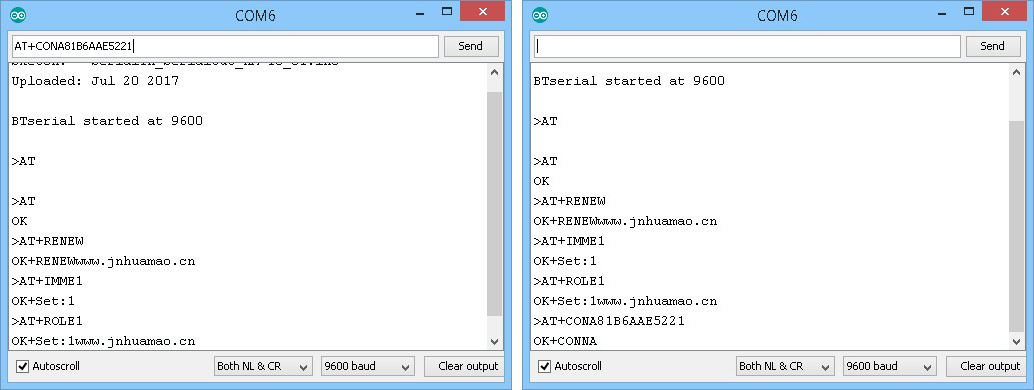
- AT+CON[ADDRESS]
- AT+PIO21 and AT+PIO20
“AT+PIO21” sets pin PIO 2 HIGH and “AT+PIO20” sets it LOW.
Make sure we are communicating by using “AT” and then reset to the default settings with “AT+RENEW”.
Set to manual connection with “AT+IMME1”
Set to Central mode with “AT+ROLE1”
If you are using an older firmware you will need to reset the module before continuing.
Connect to the Peripheral mode module with “AT+CON88C255122F9E”. If the connection is successful the HM-10 will reply with “OK+CONNA” and the LEDs on the 2 HM-10s will stop flashing and be steady on.
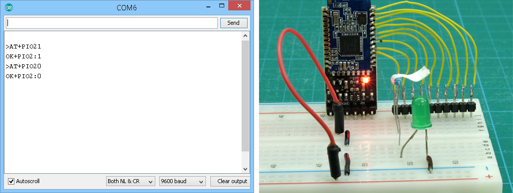
To turn the LED on, use “AT+PIO21”
and “AT+PIO20” should turn it off
Note. Depending on the power on and the on-connection settings, the LED may come on when the remote HM-10 is powered or when a connection is made. The PIO pin setting can be set for power on using the “AT+BEFC” command (before connection)and the pin settings can be set when a connection is established using the “AT+AFTC” command (after connection).
Automating the process
Since the remote device is already set up we do not need to change it. We can set the Central mode HM-10 to auto-connect on start up using the “AT+IMM0” command.
If you wish to stop the Central mode module auto connecting, turn off the remote HM-10.
On the Central mode module enter:
- AT
- AT+RENEW
- AT+ROLE1
“AT+RENEW” resets the HM-10 to the default factory settings and since IMME0 is the default setting, we do not need to change it.
Now, when the modules are powered on they should auto connect.
Now add a push button switch to pin D2.

and now upload the following sketch.
// HM-10_Example_03_MODE2_LED
//
//  Simple remote control using HM-10s: LED on. LED off
//  HM-10 in Central mode connected to an Arduino
//  HM-10, no Arduino, LED connected to PIO 2
//
//  Pins
//  BT VCC to Arduino 5V out.
//  BT GND to GND
//  Arduino D8 (ASS RX) - BT TX no need voltage divider
//  Arduino D9 (ASS TX) - BT RX through a voltage divider
//

#include
AltSoftSerial BTserial;

byte switchPin = 2;
boolean switch_State = LOW;
boolean oldswitch_State = LOW;


void setup()
{
    Serial.begin(9600);
    Serial.print("Sketch:   ");   Serial.println(__FILE__);
    Serial.print("Uploaded: ");   Serial.println(__DATE__);
    Serial.println(" ");

    BTserial.begin(9600);
    Serial.println("BTserial started at 9600");
    Serial.println("");

    pinMode(switchPin, INPUT);
}


void loop()
{
    // Very simple debouce.
    boolean state1 = digitalRead(switchPin); delay(1);
    boolean state2 = digitalRead(switchPin); delay(1);
    boolean state3 = digitalRead(switchPin); delay(1);
    if ((state1 == state2) && (state1==state3))
    {
        switch_State = state1;

        if (switch_State != oldswitch_State)
        {
              if ( switch_State == HIGH) { BTserial.print("AT+PIO21" );  Serial.println("The LED is ON"); }
              else                       { BTserial.print("AT+PIO20" );  Serial.println("The LED is OFF"); }

              oldswitch_State = switch_State;
        }
    }
}
The sketch is fairly simple. When the button switch is pressed “AT+PIO21” is sent to the remote HM-10. When the switch is released, “AT+PIO20” is sent.
“AT+PIO21” sets PIO-2 HIGH and turns on the LED.
“AT+PIO20” sets PIO-2 LOW and turns off the LED.
Hi, great tutorial and I’m moments away from purchasing a couple of these things but do you happen to know what happens to any altered pin states should the central mode device lose power/connection with the peripheral device in a remote control situation – say I remotely set a normally low pin to high on the peripheral device to turn on an LED, will the remote device then set that pin low again immediately (or at least back to its confgured pre-connection state?) if the connection drops out? Thanks!
I haven’t tried this. If I get time at the weekend I will try a few experiments.
When a new connection is established the pin(s) will be set based on the AFTC settings.
I don’t know if losing the connection uses the BEFC settings or not. When I get time I will try.