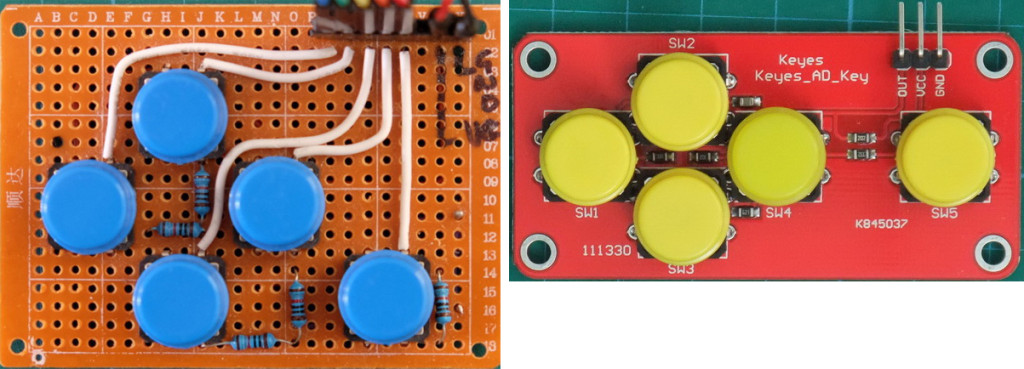
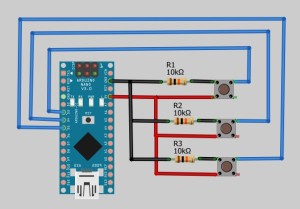
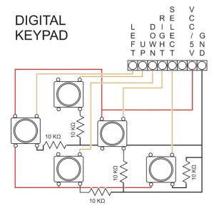
Digial keypad on the left. Analogue keypad on the right.
When I first started building the dropController and the camController I could not find suitable navigation keypads, the ones I did find were expensive or not really suitable, so I built my own. These were simple keypads and follow the normal wiring for press button switches. This means each of the push button switches is wired to a separate pin on the Arduino. This obviously means you need 5 pins. This was fine until I wanted to add extra solenoid valves and realized I didn’t have enough spare pins.
I starting looking for pre-made keypads again and came across the Keyes Keypad on Taobao. These are cheap and smaller than the keypads I made. They also use a single pin. These are analogue keypads that use a single analogue pin on the Arduino.
The main difference between the digital keypad and the analogue keypad is how the keys are read and how the returned value is used. For the digital keypad you need to check each pin/key separately. For example. If left_key is pressed, if right_key is pressed. The analogue keypad uses a single variable which has a different value depending on the key pressed. For example. if Keypress is left, or if keypress is up. I found this a little easier to work with but it can be written anyway you wish.
Digital Keypad

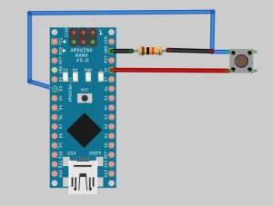
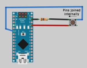
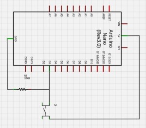
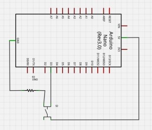
The wiring for each button switch is fairly simple. There is a GND wire with a 10K pull down resistor, a VCC/+5V wire and a data wire that goes to an Arduino digital pin. The pull down resistor gives you a reading of LOW when the button switch is not pressed. When pressed the 10K resistor is bypassed and the reading is HIGH.
Both diagrams are the same. Internally, the left and right sides of the switch are joined together. This can be seen from the schematic icon used for switches:
Making a keypad is just a case of adding more buttons.
There are many resources on the net and the Arduino site has a good introduction: http://arduino.cc/en/tutorial/button
I use Alexander Brevig’s button library for detecting key presses. This makes the code simple. At the start of the sketch you define which buttons are on which pins and if you are using pulldown (to GND) or pullup (to +5). I have always used pulldown.
Button ok_button = Button(2,PULLDOWN);
Button rt_button = Button(3,PULLDOWN);
Button dn_button = Button(4,PULLDOWN);
Button up_button = Button(5,PULLDOWN);
Button lf_button = Button(6,PULLDOWN);
Later in the main body of the sketch you can detect key presses with a simple one line statement.
ok_button.uniquePress();
This returns TRUE of FALSE and can be used in a variety of different ways. For example:
if ( ok_button.uniquePress() ) { Serial.Print( "OK button was pressed."); }
The library allows you to detect such things as unique key presses and the current button state (up or down) as well as others. The library can be found in the Arduino playground at http://playground.arduino.cc/Code/Button
Analogue Keypad
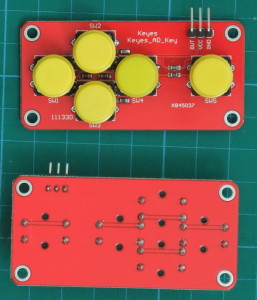
The analogue keypad produces a different voltage or analogue value depending on which key is pressed. This can be read by a single analogue pin on the Arduino. In theory this is slower than using digital pins but I have not noticed any difference and I have found that the analogue routine I use (copied from the interweb) gives a more positive response than the one I use for the digital keypad. I still get a lot of bounce and false presses with the digital keypad (not that I really did much to fix it).
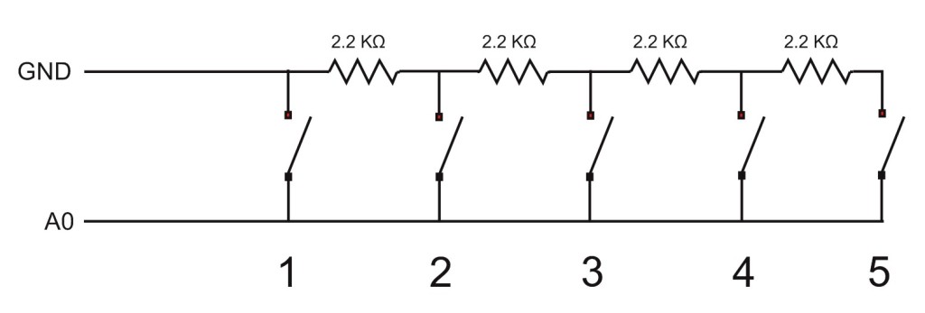
I buy the analogue keypads from Taobao in China but they are also available from ebay. It is fairly straight forward to make your own, the switches are arranged in the same way as a voltage divider (or because we have 5 switches I think it is a voltage ladder).
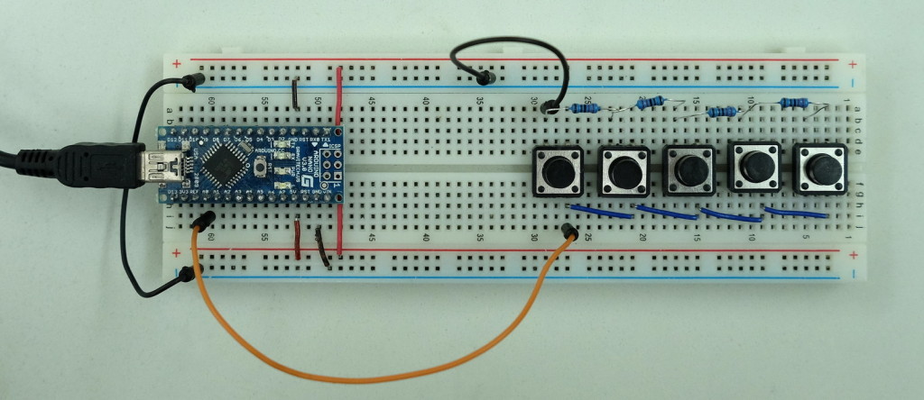
DIY Single Pin Analogue Navigation Keypad
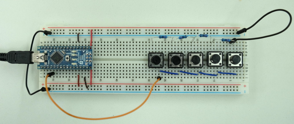
Here is a simple keypad set up on a breadboard. The wire from the button switches goes to A0 on the Arduino.
I used 2.2K ohm resistors because it is what I had but other values can be used as long as they are large enough. 1K and 2K work as well.
Keypad tester sketch
The below sketch reads the analogue pin and outputs the value to the serial monitor.
/*
Keypad Tester 01. Created by Martyn Currey
*/

// Global Variables
const byte keypadPin     = A0;
int val = 0;

void setup()
{
  Serial.begin(9600);
  while (!Serial)   {  ;    }
  Serial.println(F("Start\n"));
  // set the analogue pin for input and turn on the internal pullup resistor
  pinMode(keypadPin, INPUT_PULLUP);
}

void loop()
{
    val = getKeyValue();
    Serial.println( val );
    delay(100);
}


int getKeyValue()
{
    int pinVal;
    pinVal = analogRead(keypadPin);
    return pinVal;
}
Using 2.2KΩ resistors I get the following values:.
– No button pressed = 1021 to 1023
– First button = 14 or 15
– Second button = 72 or 73
– Third = 124
– Forth = 170
– Fifth = 212 or 213
Due to tolerances in the components you are very likely to get slightly different values.
Setting the pullup resistor on the analogue pin means it is putting a +5v (in reality is is slightly lower) on the pin which means when no button is pressed the pin reads about 1023.
You may notice that the first button switch causes a direct short from A0 to GND. The pullup resistor on the pin protects the Arduino from a short and the actual current flowing is only around 1 milliamp.
Moving the GND connection to the other end of the circuit simple reverses the values each button switch gives. i.e. pin one now gives 212 and pin 5 gives 14.
In the sketch we could just use the value returned from the analogread() but a better way would be to use direction labels. This allows you to write things like if (buttonPress==LEFT) {}, or if (buttonPress==DOWN) {}.
/*
Keypad Tester 02. Created by Martyn Currey
*/

// Global Variables
const byte NONE = 0;
const byte LEFT = 1;
const byte UP = 2;
const byte RIGHT = 3;
const byte DOWN = 4;
const byte SELECT = 5;

const byte keypadPin = A0;
byte key = 0;

void setup()
{
  Serial.begin(9600);
  while (!Serial)   {  ;    }
  Serial.println(F("Start\n"));
  pinMode(keypadPin, INPUT_PULLUP); // sets analog pin for input
}

void loop()
{
    key = getKey();
    if (key==LEFT)    { Serial.println("LEFT"); }
    if (key==RIGHT)   { Serial.println("RIGHT"); }
    if (key==UP)      { Serial.println("UP"); }
    if (key==DOWN)    { Serial.println("DOWN"); }
    if (key==SELECT)  { Serial.println("SELECT"); }
    if (key==NONE)    { Serial.println("NO KEY PRESSED"); }
    delay(100);
}


/*
Key Values
Left / First button = 15
Up / Second button = 72
Down / Third = 124
Right / Forth = 170
Select / Fifth = 212
No button pressed = 1021

Because the values change depending on the actual components and even the temperature we need to test for a range of values.
I tend to use +/- 20. This gives:
Left - 0 to 35
Up - 52 to 92
Down - 104 to 144
Right - 150 to 190
Select - 192 to 232
*/
byte getKey()
{
    int val = 0;
    byte button = 0;
    val = analogRead(keypadPin);

    button = NONE; // use NONE as the default value
    if ( val <= 35)  {  button = LEFT; }                                // left
    else if ( (val >= 52)  &&  (val <=92)    )   {  button = UP;  }     // up
    else if ( (val >= 104) &&  (val <= 144 ) )   {  button = DOWN;  }   // down
    else if ( (val >= 150) &&  (val <= 190)  )   {  button = RIGHT;  }  // right
    else if ( (val >= 192) &&  ( val <=232)  )   {  button = SELECT;  } // select
    return button;
}
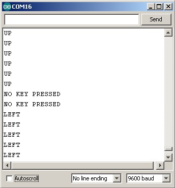
Run the sketch, open the serial monitor and you should now see something similar to:
Further Resources
There is another fairly simple example on the tronixstuff website Using analog input for multiple buttons. This is very similar to mine.
An example that uses different value resistors can be found at http://arduino-info.wikispaces.com/Keyboards-MultipleButtons. I believe this is how the pre-made keypads I buy are configured. Different value resistors spread out the range of key press values more evenly.
Exactly what I needed. Thank you.
Very useful thanks! Do you know a good expansion board that works with this code? I need to connect about 25 switches and all of them need to be readout upon start for the actual status.
Considered something lik https://www.banggood.com/4-x-4-16-Key-Matrix-Keypad-Keyboard-Module-16-Buttons-For-MCU-Arduino-p-933362.html? They may even have bigger ones. Or perhaps try some (membrane keyboard) that allows two-digit inputs?
Hi there, I tried several times to resolve the issue, but it only works for a few time then I am happy to free up 5 ports a Saturday morning, BUT a day later I become angry because the project now fails and the analog port is catching completely different values so buttons assignations are not valid or shifted :(
for 5 button & resistors array the return values are, lets say you divide your analog input 1024(max) / 5(buttons) = 204, that’s the space between each button, for an if/case arrangement it would be very straight you could catch values for the first button (0 to 204)
BUT
in Mexico we have temperatures higher than 104F during the day falling the half during nigth, I knew the resistors are influenced somehow but I noticed metal film resistors are too prone to this and would fail in some point, the values for the same button moves along the day depending on temperature and humidity, making it very very un-predictible
Have you ever face this ? I bught my resistors in china through Ebay should I try another type of resitors ?
The values will always change depending the the temperature. This is normal and why it is a good idea to use a range for each button rather than a single value.
For example UP is between 52 and 92 in the above example. If the range I use is not enough for your heat, try extending it. You will notice that I have gaps between each direction.
You can also change the resistor values. I used the same value for all buttons but you may be better using values that follow a scale. This should even out the range of numbers for each button. See http://arduino-info.wikispaces.com/Keyboards-MultipleButtons for an example.
Hi guys, I been trying to solve the issue since a long, I tried by using a temperature measure lm355 but this is really hard as in Mexico there are broad of different climates, from rainy cold to desert,
I barely stop using this technique but you could do better with a custom solution then adding the LM355 and its proper calculations,
btw,,, do not buy the chinesse Keyes 5 buttons (actually not so cheap), it overlaps values one time you have a measure of <20 on the UP button sometimes <10, later night or next day having measures [40, 60] for the down or suddenly having measures [1, 70] on the LEFT button so it overlaps the UP signals, for the purpose … it is completelly useles
experiment with different value resistors.
Thanks for this explanation, just bought this keypad for fun and was wondering how it actually works. And hell yeah, except fpr the ugly color, it will come useful.
Thanks for this tutorial, good explained, after adjusting the analog read values my keys worked as expected. cheers and thanks
Hi Martyn
Recently mastered the analogue key pad but I would now like to add dual function to the select key
ie
short press go to pre-set radio frequency
long press go to a different pre-set radio frequency.
Any ideas will be gratefully received
Thanks
thank a lot for great helpful referent
Can I use 20 buttons with 2K resistor & A0 & GND to Arduino with DF player 20 MP3 sounds? 01 sound effect 1 02 sound effect 2 etc?
google keypad matrix
Hi! Can I use 20 buttons 1 analog input 19 resistors & GND? Thanks :)